Mitsubishi Outlander 3rd generation was produced in 2012, 2013, 2014, 2015, 2016, 2017, 2018, 2019, 2020 under the name Mitsubishi Outlander P-HEV. During this time, the model has undergone restyling. In this material you will find a description of the fuses and relays of the Mitsubishi Outlander 3 with block diagrams and their locations. Let’s highlight the fuse responsible for the cigarette lighter.
The design of the blocks may vary and depends on the year of manufacture and equipment level. Compare the description with your diagrams on the back of the cover.
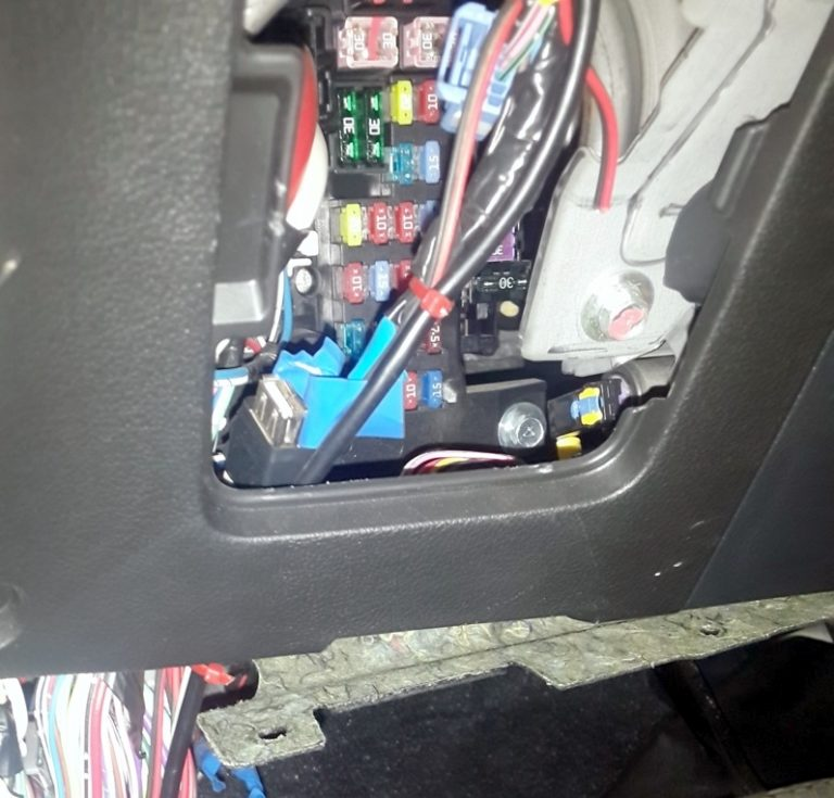
Cabin block
It is installed under the driver’s panel behind a protective cover.
Description
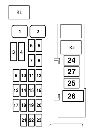
| 1 | 30A Power windows |
| 2 | 30A Rear window heater |
| 3 | 30A Heater |
| 4 | 30A Windshield wiper |
| 5 | 20A Electric door lock actuator |
| 6 | 10A Rear fog light |
| 7 | 15A Power outlet |
| 8 | 10A Rear window wiper |
| 9 | 20A Luke |
| 10 | 10A Ignition switch |
| 11 | 10A Options |
| 12 | 12A Emergency light alarm |
| 13 | 13A All-wheel drive system |
| 14 | 15A Brake lights (brake light bulbs) |
| 15 | 10A Instrument panel |
| 16 | 7.5A SRS safety system |
| 17 | 15A Audio system |
| 18 | 7.5A Control unit relay |
| 19 | 15A Interior lighting lamps (ceiling lights) |
| 20 | 7.5A Reversing lights (reversing light bulbs) |
| 21 | 7.5A Heated exterior rear-view mirrors |
| 22 | 10A Exterior rear-view mirrors |
| 23 | 15A Cigarette Lighter/Power Outlet |
| 24 | 7.5A Charging system |
| 25 | 30A Electric seat drive |
| 26 | 30A Seat heating |
| 27 | Reserve |
Fuse number 23 at 15A is responsible for the front cigarette lighter.
Blocks under the hood
Under the hood of the Mitsubishi Outlander 3, there may be 2 fuse and relay blocks – on the left and right of the engine compartment.
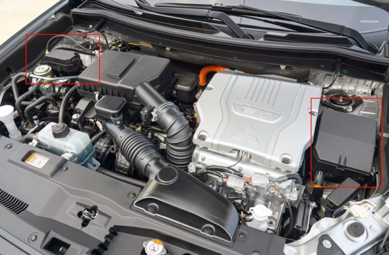
Main unit
It is established by law.
Photo – example

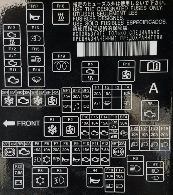

Marking
| SBF1 | 30A Condenser fan motor |
| SBF2 | 30A Starter |
| SBF3 | 30A Condenser fan motor |
| SBF4 | 40A Engine cooling system fan motor |
| SBF5 | 40А ABS |
| SBF6 | 40А VLC |
| SBF7 | 30А ABS |
| BF1 | 30A Electric tailgate drive |
| BF2 | 30A Audio system amplifier |
| BF3 | 30A Input/Output Device |
| BF4 | 30A Diesel engine electrical equipment |
| F1 | 20A automatic transmission |
| F2 | 15A Wiper blade heater |
| F3 | Reserve |
| F4 | 10A Daytime running lights |
| F5 | 15A Fog lights |
| F6 | 10A Air conditioner |
| F7 | 20A Headlight washers |
| F8 | 20A Anti-theft alarm sound |
| F9 | 10A Audible signal |
| F10 | 15A Throttle actuator |
| F11 | 7.5A Generator |
| F12 | 7.5A Motor |
| F13 | 20A Engine electrical equipment power supply circuit |
| 25A Fuel rail heater | |
| F14 | 15A Fuel pump |
| F15 | 10A Ignition coil |
| F16 | 10A Engine electrical equipment power supply circuit |
| F17 | 10A High beam headlight (left) |
| F18 | 10A High beam headlight (right) |
| F19 | 20A With gas discharge lamp: Low beam headlight (left) |
| F20 | 20A With gas discharge lamp: Low beam headlight (right) |
| F21 | 10A With halogen lamp: Low beam headlight (left) |
| F22 | 10A Low beam headlight with halogen light (right) bulb |
| F23 | 7.5A Battery charge sensor |
Additional unit
Not all models are installed.
Scheme
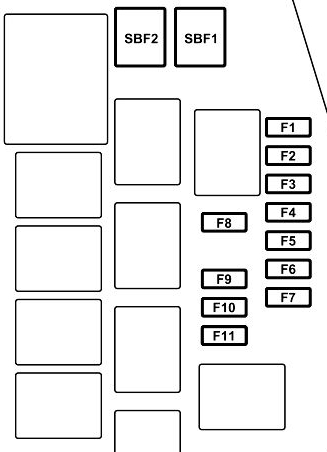
Transcript
| SBF1 | 30A Chamber |
| SBF2 | 30A Vacuum pump |
| F1 | 20A Water pump (electric motors) |
| F2 | 7.5A Battery Management |
| F3 | 15A Heater power battery |
| F4 | 7.5A Fuel tank flap |
| F5 | 7.5A Air conditioner solenoid |
| F6 | 7.5A Air conditioning pump |
| F7 | 10A Electric motor controller |
| F8 | 7.5A Windshield heating |
| F9 | 15A Main Battery Driver / 10A Power Supply and Charge Controller |
| F10 | 15A Ignition controller |
| F11 | 7.5A Ignition controller |
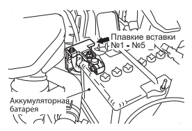
Battery unit
A safety block made in the form of high-power fuses can also be attached to the positive terminal of the battery.