Hyundai i30 1st generation was produced in 2007, 2008, 2009, 2010, 2011 and 2012 with hatchback and station wagon bodies, with both gasoline and diesel engines. During this time, the model has undergone a small update. In this publication you will find a description of the fuses and relays of the first generation Hyundai i30 with block diagrams and their locations. We note the cigarette lighter fuse.
The design of the blocks depends on the year of manufacture, check the purpose with your diagrams on the back of the protective cover.
Blocks in the cabin
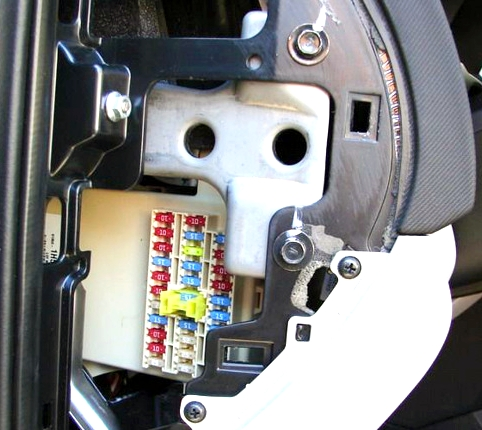
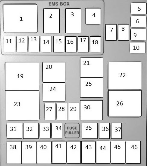
Fuse block
Located on the left side of the instrument panel behind a protective cover.
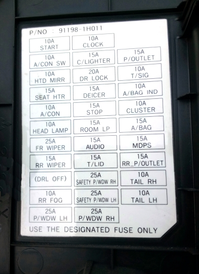
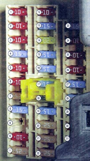
Fuse designations
| 1 | 10A Starter Relay – START |
| 2 | 10A Air conditioning control unit – A/CON SW |
| 3 | 10A Heated exterior rear-view mirror system – HTD MIRR |
| 4 | 15A Seat heating – SEAT HTR |
| 5 | 10A Air conditioner – A/CON |
| 6 | 10A High beam lamps – HEAD LAMP |
| 7 | 25A Windshield wiper – FR WIPER |
| 8 | 15A Rear door wiper – RR WIPER |
| 9 | 15A Turning on the dipped beam headlights during the day – DRL OFF |
| 10 | 10A Rear fog lights – RR FOG |
| 11 | 25A Power Window Control Unit – P/WDW LH |
| 12 | 10A Clock – CLOCK |
| 13 | 15A Cigarette lighter – C/LIGHTER |
| 14 | 20A Sunroof, ignition control unit relay – DR LOCK |
| 15 | 15A Windshield Defroster Relay – DEICER |
| 16 | 15A Stop signals – STOP |
| 17 | 15A Interior lighting – ROOM LP |
| 18 | 15A Audio system, trip computer – AUDIO |
| 19 | 15A Rear 5th door – T/LID |
| 20 | 25A Power window lock (right side) – SAFETY P/WDW RH |
| 21 | 25A Power window lock (left side) – SAFETY P/WDW LH |
| 22 | 25A Power windows – P/WDW |
| 23 | 15A Power Outlet – P/OUTLET |
| 24 | 10A Switch Block – T/SIG |
| 25 | 10A Airbag warning light – A/BAG IND |
| 26 | 10A Instrument panel – CLUSTER |
| 27 | 15A Airbag – A/BAG |
| 28 | 15A Door or Ignition Control Module – IGN1-A |
| 29 | 15A Front Power Outlet – RR P/OUTLET |
| 30 | 10A Rear right side marker light – TAIL RH |
| 31 | 10A Rear left side marker light – TAIL RH |
Fuse number 13 at 15A is responsible for the cigarette lighter.
Relay blocks
There may be 2 additional relay blocks under the panel.
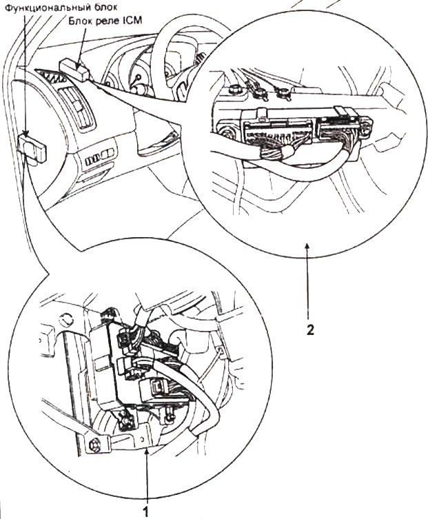
Relay location in blocks
- rear light relay, power window relay, heater relay, tailgate relay
- central locking relay, windshield defroster relay, rear fog light relay, anti-theft alarm horn relay, rain sensor relay, Built-in-ICM relay block
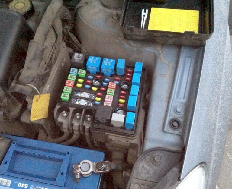
Blocks under the hood
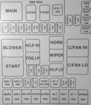
Main unit
The main unit with fuses and relays is located on the left side, next to the battery and covered by a protective cover.
Option 1
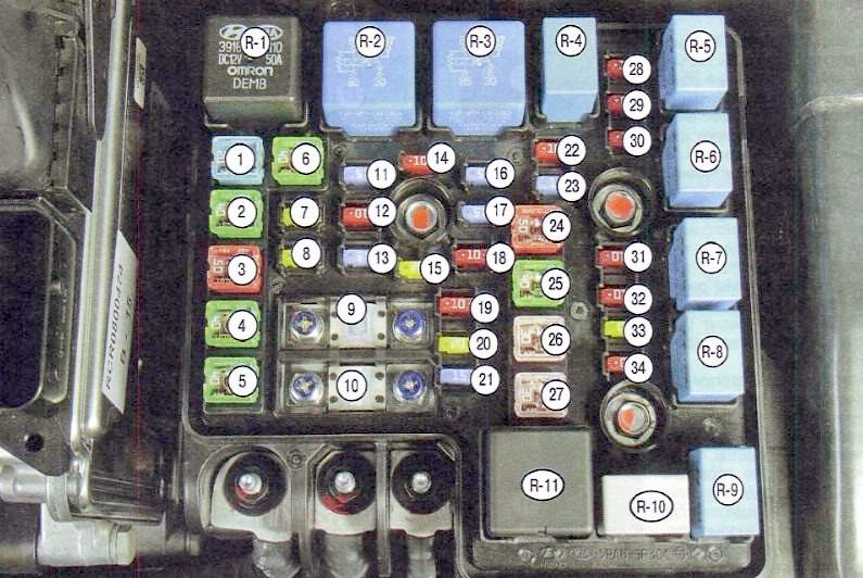
Appointment
| 1 | 20A ABS and ESP – ABS2 |
| 2 | 40A ABS and ESP |
| 3 | 50A Electronic control unit for interior electrical equipment – B+1 |
| 4 | 40A Heated rear view mirrors – RR HTD |
| 5 | 40A Electric fan – BLOWER |
| 6 | 40A Electric fan of the air conditioning system – C/FAN |
| 7 | 20A Headlight washer – H/LP WASHER |
| 8 | 20A Reserve – SPARE |
| 9 | 125A Generator – ALTERNATOR |
| 10 | 80A Electric Power Steering – MDPS |
| 11 | 15A Front fog lights – FR FOG |
| 12 | 10A Air conditioner – A/CON |
| 13 | 15A Emergency alarm – HAZARD |
| 14 | 10A Reserve – SPARE |
| 15 | 20A Reserve – SPARE |
| 16 | 15A Fuel Pump – F/PUMP |
| 17 | 15A Reserve – SPARE |
| 18 | 10A Engine Control Unit – ECU1 |
| 19 | 10A Engine Control Unit – ECU2 |
| 20 | 20A Engine Control Unit – ECU3 |
| 21 | 15A Fuel injectors, air conditioning system – INJ |
| 22 | 10A Sensors – SNSR2 |
| 23 | 15A Sound signal – HORN |
| 24 | 50A Electronic control unit for interior electrical equipment – B+2 |
| 25 | 40A Starter, ignition switch (lock) – ING2 |
| 26 | 30A Ignition switch (lock) – IGN1 |
| 27 | 30A Main relay – ECU |
| 28 | 10A ESP stability control system, ABS anti-lock braking system, ABS stability control sensor |
| 29 | 10A Ignition system – ECU2 |
| 30 | 10A Reverse light switch – B/UP |
| 31 | 10A Right headlight low beam – H/LP LO RH |
| 32 | 10A Left headlight low beam – H/LP LO LH |
| 33 | 20A High beam headlights – H/LP HI |
| 34 | 10A Sensors – SNSR1 |
| R1 | Cooling system electric fan relay (low speed) – C/FAN2 |
| R2 | Cooling system electric fan relay (high speed) – C/FAN1 |
| R3 | Starter relay – START |
| R4 | Fuel pump relay – F/PUMP |
| R5 | Air conditioner relay – A/CON |
| R6 | Headlight low beam relay – H/LP LO |
| R7 | Horn relay – HORN |
| R8 | High Beam Headlight Relay – H/LP HI |
| R9 | Rear fog lamp relay – FOG LP |
| R10 | Wiper relay – WIPER |
| R11 | Main relay – MAIN |
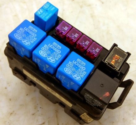
Option 2
Photo – example
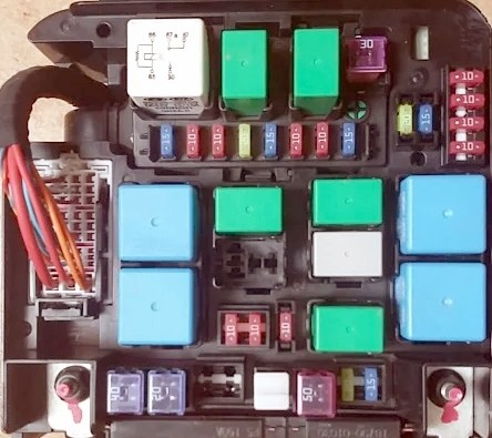
Transcript
- Main relay
- Air conditioning
- Fuel pump
- Engine control unit
- ABS ta ESP
- Reverse lamp switch
- Reserve
- Reserve
- Main relay
- Reserve
- Sensors
- Engine control unit
- Sensors
- Reserve
- Fuel injectors, air conditioning system.
- Air conditioning
- Engine control unit
- Fuel pump
- Electric fan
- High beam relay
- Sound signal
- High fan speed
- Starter relay
- Rear fog lights
- Glass cleaner
- Low speed fan
- Left dipped beam
- Right dipped beam
- Reserve
- Low beam relay
- ABS ESP
- ABS ESP
- Front fog lights
- Reserve
- Electronics unit
- Reserve
- Sound signal and its relay
- Electric power steering
- Starter and ignition switch
- Heated mirrors
- Fan (air conditioner)
- Electric fan
- Generator
- Ignition switch
- Interior control unit
- Reserve
Check the assignment with your diagram on the back of the protective cover.
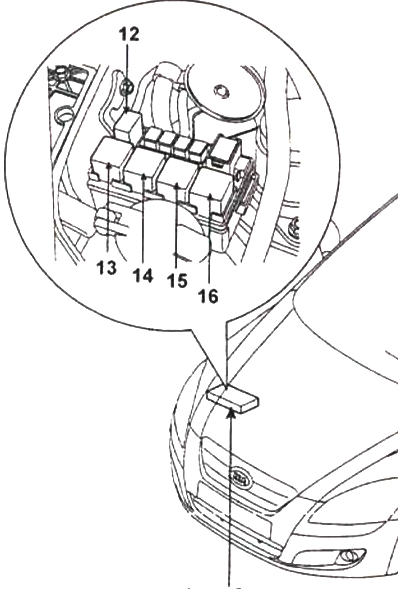
Description
- 12 – fuel filter heater relay
- 13 – PTC heater relay #3
- 14 – PTC heater relay #2
- 15 – PTC heater relay #1
- 16 – glow plug relay