The Mitsubishi Delica 4th generation minivan was produced in 1994, 1995, 1996, 1997, 1998, 1999, 2000, 2001, 2002, 2003, 2004, 2005, 2006. It was supplied worldwide. In some countries it is known as the Mitsubishi L400, Mitsubishi Space Gear. The cargo model is called – Delica Cargo . In this publication you will find a description of the fuses and relays of the Mitsubishi Delica 4th generation with block diagrams and locations. Let’s highlight the fuse responsible for the cigarette lighter.
Depending on the region of delivery and the level of equipment, there may be differences in the design of the blocks and the purpose of their elements.
Blocks in the cabin
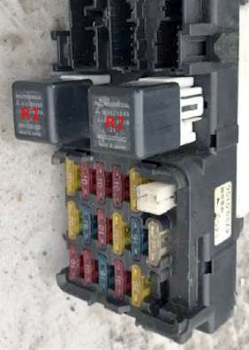
Fuse and relay block
Located at the bottom of the instrument panel on the left side.
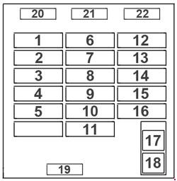
Description
| 1 | 10A Audible signal |
| 2 | 10A Heater |
| 3 | 15A Cigarette lighter |
| 4 | 10A Automatic transmission control system |
| 5 | 20A Electric blinds (right-hand drive models) |
| 6 | 20A Rear window heater |
| 7 | 15A Seat heating (except models manufactured since 2000) |
| 8 | 10A Control and measuring instruments |
| 9 | 20A Windshield washer and wiper |
| 10 | 15A ETACS system and central locking (right-hand drive models from 1998) |
| 11 | 25A Front heater fan |
| 12 | 20A Rear heater fan |
| 13 | 10A ECS and ABS systems |
| 14 | 10A Rear code lights |
| 15 | 10A Turn signals and hazard warning lights |
| 16 | 20A Socket for connecting additional |
| 17 | Heated rear window |
| 18 | Heater |
| 19 | Spare fuse |
| 20 | Spare fuse |
| 21 | Spare fuse |
| 22 | Spare fuse |
Fuse number 3 at 15A is responsible for the cigarette lighter.
- R1 – Rear window defroster relay
- R2 – Front heater fan motor relay
Relay block
It is mounted near the fuse box.
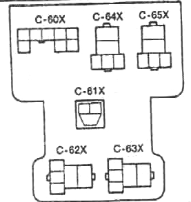
Marking
- C-60X – Central lock relay
- C-61X – Relay – interrupter for turn signals and emergency alarm
- C-62X – Rear heater fan motor relay
- C-62X – Rear heater fan motor Hi mode relay
- C-63X – Auxiliary heater connection socket relay
- C-64X – Rear clearance relay
- C-65X – Electric window lifter relay
Block under the hood
Located to the right of the engine compartment.
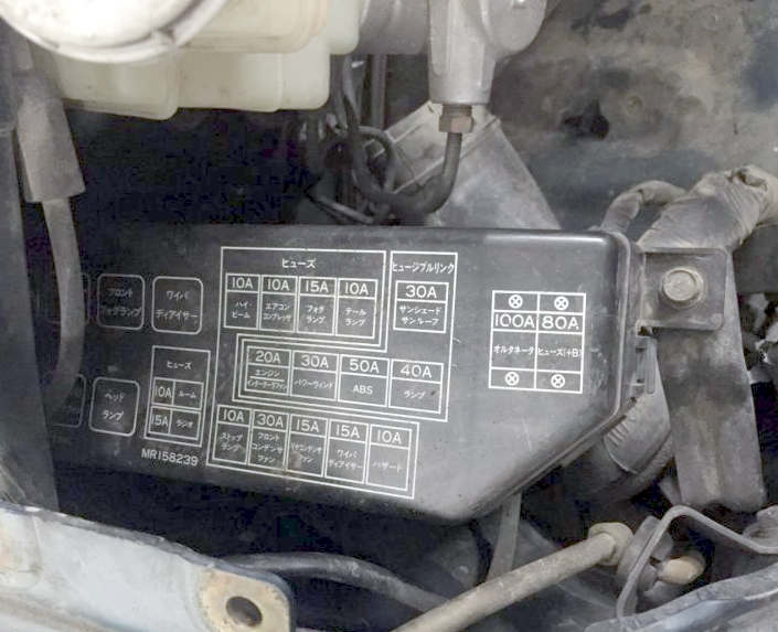
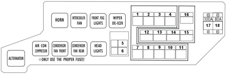
Purpose of fuses
| 1 | 10A High beam headlights |
| 2 | 10/15A Air conditioning compressor |
| 3 | 10A Dimensions (left) (left-hand drive models) |
| 3 | 15A Fog lights (right-hand drive models) |
| 4 | 10A Dimensions (right for left-hand drive models) |
| 5 | 10A Interior lighting |
| 6 | 15A Radio, Socket for connecting additional equipment |
| 7 | 10A Stop signals |
| 8 | 20/30A Front condenser electric fan |
| 9 | 10/15A Side condenser electric fan |
| 10 | 15A Fuel Heater Wire (left-hand drive models) |
| 10 | 15A Wiper blade heater (right-hand drive models) |
| 11 | 10A Emergency alarm |
| 12 | 20A Intercooler |
| 13 | 30A Electric window lifter, Central locking |
| 14 | 50A ABS system |
| 15 | 40A Outdoor lighting |
| 16 | 30A Electric sunroof and sunshade |
| 17 | 100A Generator |
| 18 | 80A Accumulator, battery |
Relay decoding
- ALTERNATOR – Generator
- AIR CON COMPRESSOR – air conditioning compressor
- CONDENSOR FAN FRONT – Front fan condenser
- CONDENSOR RAER FRONT – Rear fan condenser
- HEAD LIGHT – Headlight relay
- HORN – Signal relay
- INTERCOOLER FAN – Intercooler fan relay
- FRONT FOG LIGHT – Front fog light relay
- WIPER DE-ICER – Wiper and heater relay
Fuses in the form of a high-power fuse link can also be installed on the positive terminal of the battery.