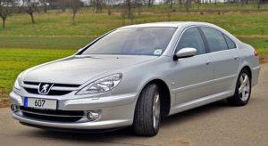
Peugeot 607 belongs to business class cars. It was produced in 1999, 2000, 2001, 2002, 2003, 2004, 2005, 2006, 2007, 2008, 2009 and 2010. During this period, the car underwent a small update, which did not affect the design features. Due to the rich equipment and periodic modification, different versions of fuse blocks are possible. We will present the location of all electronic control units, a description of the fuse block and relay circuits of the Peugeot 607.
Location of electronic control components
General scheme
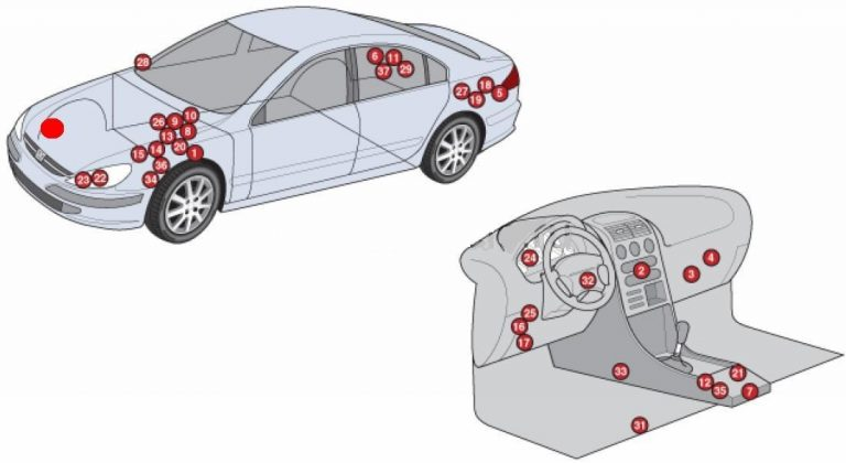
Description
| 1 | ABS electronic control unit |
| 2 | Electronic air conditioning control unit |
| 3 | Air conditioner/heater fan motor control unit |
| 4 | Anti-theft system control unit |
| 5 | Rechargeable battery |
| 6 | Trunk lid opening/closing drive control unit – on the right side of the luggage compartment |
| 7 | Diagnostic Connector (DLC) |
| 8 | Electronic engine control unit (ECM) |
| 9 | Cooling system fan motor relay 1 |
| 10 | Cooling system fan motor relay 2 |
| 11 | Additive supply control unit – on the right side of the luggage compartment |
| 12 | Fuse/Relay Block, Center Console – Diesel |
| 13 | Fuse/relay block, engine compartment 1 |
| 14 | Fuse/relay block, engine compartment 2- under the fuse/relay block in the engine compartment |
| 15 | Fuse/relay block, engine compartment Z |
| 16 | Fuse/relay block, instrument panel 1 |
| 17 | Fuse/relay block, instrument panel 2 |
| 18 | Fuse/relay block, luggage compartment1 |
| 19 | Fuse/relay block luggage compartment 2 |
| 20 | Glow plug control unit |
| 21 | Heater fan motor relay |
| 22 | Sound signal 1 |
| 23 | Beep 2 |
| 24 | Instrument cluster control unit |
| 25 | Multifunction control unit 1 – built into fuse/relay block 1 of the dashboard – functions: Central locking, rear window heater, immobilizer, turn signals/hazard alarm, brake lights, rear clearance lights. Windshield washer |
| 26 | Multifunction control unit 2 – built into the fuse/relay block 1 in the engine compartment – functions: Air conditioning system. cooling system fan motor, engine management, fog lights, horn, windshield wipers |
| 27 | Multifunction control unit 3 – built into the fuse/relay block 2 in the luggage compartment – functions: Trailer electrical connector |
| 28 | Ambient air temperature sensor in the door rearview mirror |
| 29 | Parking system control unit – on the right side of the luggage compartment |
| 30 | Power steering control unit |
| 31 | Electric seat control unit |
| 32 | Steering column electrical control unit |
| 33 | SRS electronic control unit |
| 34 | Suspension control unit |
| 35 | Telephone control unit |
| 36 | Electronic transmission control unit (TMU) |
| 37 | Tire pressure monitoring system control unit – in the right side of the luggage compartment |
The design options for the sides, as well as the number of elements in it, depend on the equipment and year of manufacture of the car.
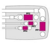
Fuse blocks in the engine compartment
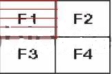
Main unit – Option 1
Block photo
Marking
| 1 | Horn relay |
| 2 | Starter relay |
| 3 | Exhaust air pump relay |
| 4 | Selector lock relay (range “P”) |
| F1 | (70 A) Intelligent switching unit (rear window heating, exterior mirrors, window cleaner, washer) |
| F2 | (50A) Cooling system fan motor |
| F3 | (50A/60A) ABS/ESP system |
| F4 | (40A) Air conditioner/heater fan motor |
| F5 | (20A) Sound signal |
| F6 | (20A) Seat heater – front left and rear left |
| F7 | (20A) Seat heater – front right and rear right |
| F8 | (70A) Intelligent switching unit. |
| F9 | (30A) Electric seat drive |
| F10 | (20A) Headlight low beam relay – automatic activation unit |
| F11 | (70A) Intelligent switching unit |
| F12 | (70A) Ignition switch. Anti-theft system power supply circuit. |
| F13 | (20A) Lighting control unit |
| F14 | (15A) Dual injection system relay power supply circuit |
| F15 | – |
| F16 | – |
| F17 | (30A) ABS/ESP system |
| F18 | (30A) Starter |
| F19 | (20A) Suspension control system |
| F20 | (10A) Engine cooling fan relay, auxiliary brake light switch, clutch and manual transmission sensor |
| F21 | (5A) Transmission control |
| F22 | (25A) ABS/ESP system |
| F23 | (15A) Diesel fuel heating unit |
| F24 | (5A) Engine control |
| F25 | (10A) Fuel pump |
| F26 | (30A) Electric seat control unit |
| F27 | (25A) Relay Block |
| F28 | (10A) Throttle valve heating circuit, injection system control solenoid valve, flow meter, oil heating |
| F29 | (10A) Additive addition system |
| F30 | – |
| F31 | (5A) Transmission control |
| F32 | (10A) Electronic unit of the dynamic stabilization system or electronic unit of ABS |
| F33 | (15A) Automatic transmission electronic control unit (except reversing lights) |
| F34 | (5A) Oxygen sensor, exhaust gas recirculation solenoid valve, turbo boost pressure regulator valve. |
Main unit – Option 2
Scheme
Transcript
- F1 20 A Switching on the relay of the electric cooling fan, additional fan (for the V6 HDI engine), engine computer power relay.
- F2 15 A Sound signal.
- F3 10 A Front and rear window washers.
- F4 20 A Headlight washer.
- F5 15 A Fuel pump and absorber unloading solenoid valve.
- F6 10 A Power steering, suspension ECU, automatic transmission.
- F7 10 A Engine ECU, ESP system ECU.
- F8 15 A Starter winding circuit.
- F9 10 A Level sensor, interior heating (HDI), brake light contactor.
- F10 30 A Engine control unit sensors (ignition coil, solenoid valves, oxygen sensors, computers, injectors).
- F11 40 A Air conditioning fan relay.
- F12 30 A Windshield wiper relay.
- F13 40 A Power supply for the intelligent switching unit (+ from the ignition switch).
- F14 30 A Turbocharger (on gasoline engines).
Main unit – Option 3
Scheme
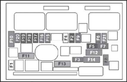
Appointment
- F1 20 A Engine power system microprocessor.
- F2 15 A Sound signal.
- F3 10 A Electric drive for the rear window blind.
- F4 20 A Headlight washer.
- F5 15 A Fuel pump (except HDI 16V 2 l. and HDI 16V 2.2 l. engines), diesel fuel preheating unit (on HDI 16V 2 l.), turbocharger and diesel fuel preheating unit (on HDI 24V 2.7 l.). , Electronic engine management system components (on HDI 16V 2.2 l.).
- F6 10 A Power steering, suspension ECU, automatic transmission, automatic headlight range control unit.
- F7 10 A Engine air flow sensor, ESP system ECU.
- F8 2 5 A Starter winding circuit.
- F9 10 A Coolant level sensor, interior heating system (HDI), brake signal contactor.
- F10 30 A Components of the electronic engine management system (injectors, ignition coil, solenoid valves, oxygen sensors).
- F11 40 A Air conditioning fan relay.
- F12 30 A Wiper relay.
- F13 40 A Power supply for the intelligent switching unit (+ from the ignition switch).
- F14 30 A Turbocharger.
- F15 10 A Right high beam headlight.
- F16 10 A Left high beam headlight.
- F17 15 A Left dipped beam headlight.
- F18 15 A Right dipped beam headlight.
- F19 15 A Oil vapor heater (on 16V 2.2 l and HDI 16V 2 l), intake air heating system solenoid valve (on HDI 16V 2 l), air flow sensor (on HDI 16V 2 l and V6 HDI 24V 2.7 l), high pressure pump (on HDI 16V 2.2 l), oxygen sensor, adsorber unloading solenoid valve (V6 24V 3 l).
- F20 10 A Water in diesel fuel sensor (on HDI 16V 2 l. and HDI 16V 2.2 l.), high pressure pump (on V6 HDI 24V 2.7 l.), turbocharger regulator solenoid valve (on HDI 16V 2 l.), distribution and exhaust system solenoid valves (on V6 24V 3 l.).
- F21 10 A Engine cooling fan relay control, auxiliary fan relay control (on V6 HDI 24V 2.7 l).
1st additional block
Located under the main one.
General scheme
Description
| F1 | – |
| F2 | (20A) Suspension control system |
| F3 | (80A) |
| F4 | (40A) Air conditioner/heater fan motor |
| F5 | (80A) |
| F6 | (20A) ABS/ESP system |
| F7 | (50A) ABS/ESP system |
| F8 | (80A) |
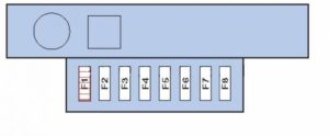
Second additional block
Appointment
| F1 | (50A) Cooling system fan motor |
| F2 | (60A) Glow plug control unit |
| F3 | (80A) Auxiliary heater |
| F4 | (50A) Cooling system fan motor |
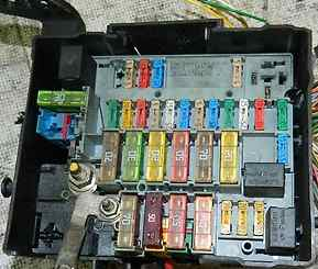
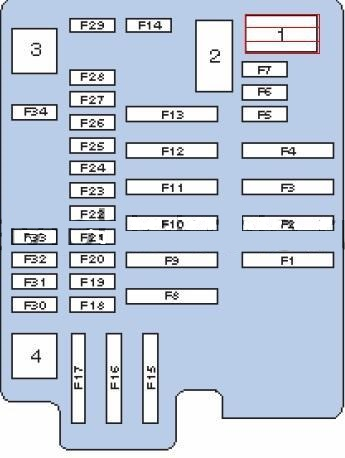
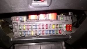
Fuses in the Peugeot 607 cabin
This unit is located in the instrument panel, bottom left.
Option 1
Block photo
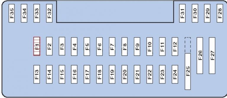
Transcript
| F1 | (30A) Central locking |
| F2 | (20A) Audio system |
| F3 | (30A) Windshield washer |
| F4 | (30A) Rear window electric drive |
| F5 | (15 A) Electronic anti-theft system, monochrome display or electronic control unit with color display, instrument panel, electronic control unit for air conditioning, car radio/radio telephone |
| F6 | (10A) Stop signals |
| F7 | (10A) Switches, toggle switches, rear ashtray light, front lamp, rear lamp, rear cigarette lighter, rear license plate lights, headlight regulator. |
| F8 | (10A) Diagnostic connector, electronic headlight regulator unit, remote radio lock control unit, interior air temperature sensor, tire pressure monitoring unit. |
| F9 | (20A) Headlight washers |
| F10 | (20A) Glove box lamp, front cigarette lighter, front and rear lights, interior rear-view mirror, electrically operated exterior rear-view mirrors. |
| F11 | (5A) Automatic lighting unit, airbag system, automatic lighting circuit relay. |
| F12 | (30A) Rear window electric drive |
| F13 | (30A) Windshield wiper |
| F14 | – |
| F15 | (15A) Electric window lifter |
| F16 | (15A) Rear cigarette lighter Peugeot 607 |
| F17 | (5A) Heated door mirrors |
| F18 | (15A) Stop signals |
| F19 | (10A) Parking assistance system unit, on-board navigation system unit |
| F20 | (15A) Siren, monochrome display or electronic control unit for color display, remote radio control unit for locks, car radio/radio telephone, monochrome or color display unit for navigator, diesel fuel additive supply control unit. |
| F21 | (15A) Diagnostic connector, trailer wiring, trailer parking light relay |
| F22 | (15 A) Diesel fuel additive control unit, driver’s seat memory unit, driver’s door panel control button unit, front passenger door panel control button unit |
| F23 | (30A) Driver’s door power window, front passenger door power window, roof vent, passenger door power window buttons on these doors and on the driver’s door. |
| F24 | (10A) Rear fog lights |
| F25 | (40A) Connector (jumper) |
| F26 | (40A) Rear window heater, radio antenna amplifier |
| F27-35 | Spare |
Fuse number 10 is responsible for the front cigarette lighter.
Option 2
Scheme
Appointment
- F1 15 A Windscreen washer pump and washer fluid level sensor.
- F2 30 A Ground of the electrical circuit of the locking and superlocking system.
- F3 5 A Airbags.
- F4 10 A Clutch pedal contactor, dual-function brake system contactor, diagnostic connector, ESP dynamic stabilization sensor, photosensitive rearview mirror.
- F5 30 A Power supply for the front windows and ventilation hatch.
- F6 30 A Power supply for rear windows.
- F7 5 A Glove box contactor, general interior lighting lamps, individual lighting lamps, vanity mirror.
- F8 20 A Power supply for the multifunction display, steering column switch unit, security alarm siren, power supply for the trailer switching unit, RD4 car radio, RT3 GPS radio telephone, control units for electric mirrors and all power windows.
- F9 30 A Front and rear cigarette lighters (maximum 100 W).
- F10 15 A Fuel tank computer power supply.
- F11 15 A Automatic transmission computer, automatic transmission selector contactor, ignition lock with anti-theft device.
- F12 15 A Power supply for the trailer switch unit, hands-free headset, seat relay, seat memory switch unit, rain sensor and lighting.
- F13 5 A Power supply to the motor switching unit.
- F14 15 A Power supply for the parking sensors switch, instrument panel, air conditioning, airbag switch and pyrotechnic pretensioners.
- F15 30 A Power supply for the locking and superlocking system.
- F17 40 A Hi-Fi amplifier, heated exterior mirrors.
Fuse number 9 at 30A is responsible for the cigarette lighter.
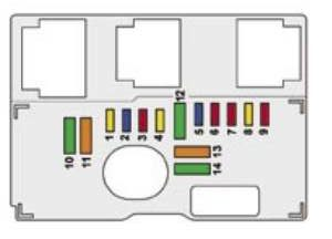
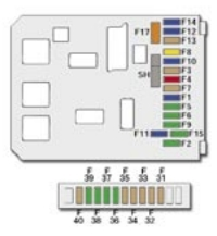
Additional unit
- F31 5 A Right brake light.
- F32 5 A Left brake light.
- F33 5 A Third brake light.
- F34 5 A Radiotelephone power supply circuit.
- F35 5 A Tire pressure monitoring system computer, CD changer.
- F36 30 A Passenger seat relay.
- F37 30 A Heated front passenger seat and rear right seat.
- F38 30 A Driver’s seat and rear left seat heating.
- F39 30 A Driver’s seat relay.
- F40 5 A Diagnostic connector.
Fuse box in the luggage compartment
It was not installed on all models. To gain access, you must open the luggage compartment lid (left).