Peugeot Expert 1st generation was produced in 1995, 1996, 1997, 1998, 1999, 2000, 2001, 2002, 2003 and 2004. During this time, the model underwent restyling. In this article, we will show a description of the fuses and relays of the Peugeot Expert 1 with block diagrams and their locations.

Cabin block
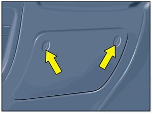
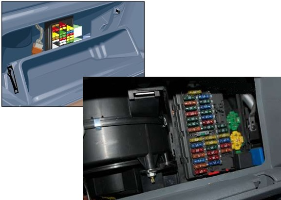
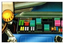
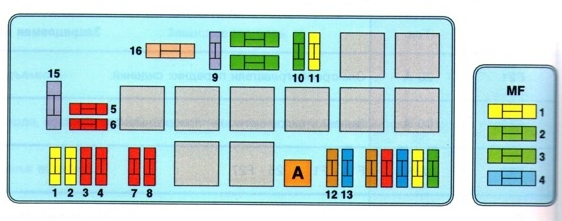
In the cabin, the main fuse box is located in the lower left part of the instrument panel.
Example of block access
Left-hand drive
Option 1
Block diagram
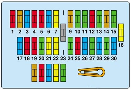
Description
- 10 A Car radio (power)
- 5 A + after ignition lock — Speed sensor — Central interior protection unit — Warning lights on the instrument panel
- 15 A Brake light – Cruise control
- 10 A Right rear light – Left front position light – Headlight adjustment
- 15 A Air conditioning — Front power windows — Climate control fan — Pressure sensor
- 15 A Heated rear window and heated seats
- 20 A Audible signal
- SHUNT –
- 5 A Headlight washers — Right front position light — License plate light — Left rear light
- 30 A Front passenger seat adjustment
- 30 A Rear windows
- 10 A ABS computer — Reversing lights — Diagnostic connector — Automatic transmission
- 30 A Driver’s seat adjustment
- 5 A Central interior protection unit (memory)
- 30 A Central interior protection unit — Central electric locking — Ceiling lights
- 20 A Cigarette lighter — Permanent (+) battery – (+) drive of additional electrical consumers
- 15 A Coolant Temperature Control Unit – Engine Cooling Fan Group
- 10 A Fog light
- 10 A Instrument panel lighting — Car radio — Side lights
- 30 A Air conditioning – Air conditioning fan
- 20 A Heated seats
- 20 A + Additional power consumers — Not used
- SHUNT F14 – F15 – F25 – F27
- 30 A Windshield washer – Front wiper
- 10 A Air conditioning — Ceiling light — Car radio memory — Digital clock
- 15 A Hazard warning lights
- 30 A Heated rear window
- 15 A Power windows – Battery discharge indicator
- 30 A Electric windows
- 15 A Interior lighting — Direction indicators — Clock — Electrically adjustable exterior mirrors
Fuse number 16 at 20A is responsible for the cigarette lighter.
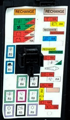
Option 2
Block diagram
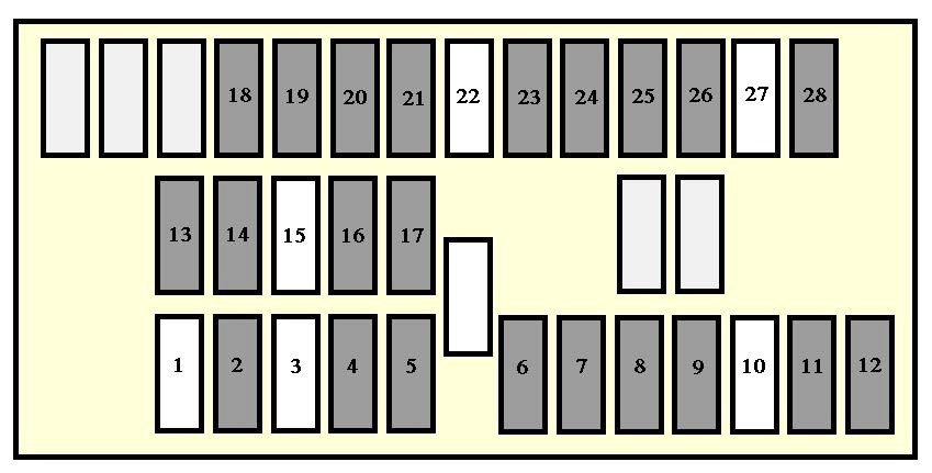
Marking
| 1 | Not used |
| 2 | 10A Diagnostic connector – ABS control unit – Reversing lights – Heated mirrors |
| 3 | Not used |
| 4 | 5A Instrument panel – speeding buzzer – speed sensor – water in diesel filter sensor |
| 5 | 15A Cruise control – Brake switch – Clutch switch – Automatic transmission – Brake lights |
| 6 | 5A Lighting – Instrument panel – Audio. |
| 7 | 30A Heated rear window |
| 8 | 30A Interior protection unit |
| 9 | 5A Interior protection unit |
| 10 | Not used |
| 11 | 5A Fan relay assembly – compressor relay |
| 12 | 10A Power windows – Fan relay – Heated seat relay – Heated rear window switch – Air conditioning |
| 13 | 15A Signal lights |
| 14 | 30A Electric windows. |
| 15 | Not used |
| 16 | 20A Heated seats |
| 17 | 20A Signal |
| 18 | 10A Rear fog light. |
| 19 | 5A Cruise control – Buzzer illumination – Seat heating switch – Dashboard lighting – Audio – Rear window heating switch – Automatic transmission lever – Hazard warning switch – Air conditioning control panel |
| 20 | 5A Headlight leveling switch – front left and front right side lights. |
| 21 | 5A Rear left and right rear position lights – Headlight washer timer – License plate light |
| 22 | Not used |
| 23 | 20A Cigarette lighter |
| 24 | 10A Audio Engineering |
| 25 | 10A Buzzer illumination – Automatic transmission buzzer – Electric mirrors – Turn signals |
| 26 | 30A Wiper Timer – Wipers – Washer Pump |
| 27 | Not used |
| 28 | 5A Instrument panel – power window relay |
Fuse number 23 is responsible for the cigarette lighter.
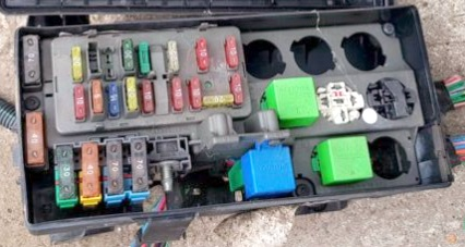
Block under the hood
Under the hood, the main fuse and relay block is located next to the battery.
Option 1
Without ABS
Example of a scheme
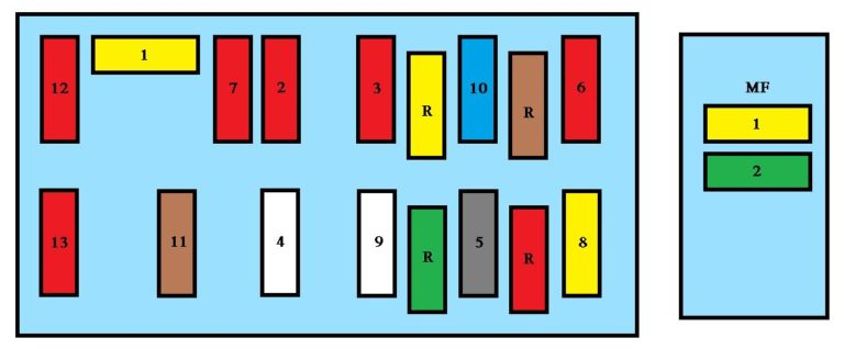
Appointment
| F1 | 20A Fuel pump |
| F2 | 10A Right dipped beam |
| F3 | 10A Left dipped beam |
| F4 | 25A Headlight Omivach |
| F5 | Schnut |
| F6 | 10A Electronic anti-theft device |
| F7 | 10A Catalytic converter sensor |
| F8 | 20A Trailer |
| F9 | 25A Cooling fan unit 1 – 120W |
| F9 | 30A Cooling fan unit 1 – 180 W |
| F10 | 15A Reserve |
| F11 | 5A Reserve |
| F12 | 10A Left high beam |
| F13 | 10A Right high beam |
With ABS
Scheme
Transcript
- 20 A Mobile home
- 20 A Fuel pump
- 10 A Left dipped beam headlight
- 10 A Right dipped beam headlight
- 10 A Diagnostic connector
- 10 A Engine immobilizer
- 10 A Left high beam headlight
- 10 A Right high beam headlight
- 25 A Engine cooling fan group 1-120 W.
- 30 A Headlight washer pump, fog lights
- 20 A Additional heating system
- 5 A Headlight Washer Timer
- 15 A Catalytic converter oxygen sensor, lambda probe heating
- –
- 40 A Air conditioning, interior fan
- 30-50 A Engine cooling fan group 1-180 W.
MF1 20A – Injection system relay, MF2 30A – Injection system relay, MF3 30A – Interior fan, MF4 40A – ABS computer.
Fuses not marked with numbers are spare.
Relay diagram
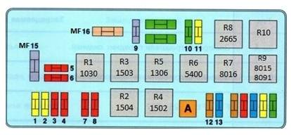
Relay designation
- R 1030 – Information about the running engine
- R 1502 / 1503 / 1504 – Fan relay
- R 5400 – Headlight washer relay
- R 8016 – Injection relay
- R 2665 – Fog light relay
Option 2
Scheme
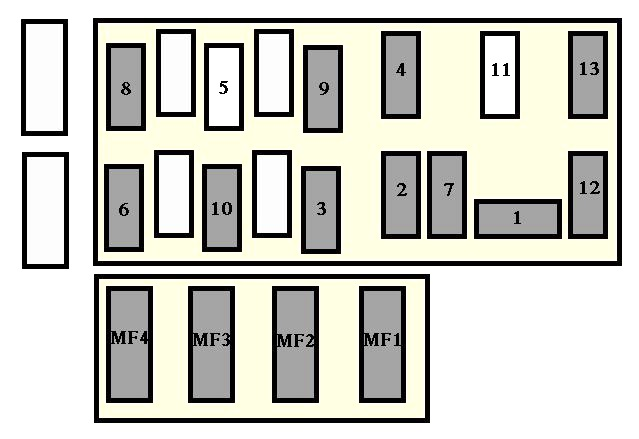
Description
| 1 | 20A Fuel pump |
| 2 | 10A Right dipped beam headlight |
| 3 | 10A Left dipped beam headlight |
| 4 | 25A Headlight Omivach |
| 5 | Shunt |
| 6 | 10A Engine immobilizer |
| 7 | 10A Catalytic converter sensor |
| 8 | 20A Towbar |
| 9 | 25A 1-120W Fan Unit |
| 9 | 30A 1-180W Fan Unit |
| 10 | 15A Fog lights |
| 11 | Not used |
| 12 | 10A Left high beam |
| 13 | 10A Right high beam |
| MF1 | 70A Engine run relay |
| MF2 | 70A ABS control unit – Ignition switch |
| MF3 | 30A Blower – Air Conditioner |
| MF4 | 30A Fan assembly |