Hyundai Solaris 1st generation was introduced in 2010. It was produced in 2011, 2012, 2013, 2014, 2015, 2016 and 2017 with sedan and hatchback bodies mainly with 1.6 and 1.8 liter gasoline engines. During this time, Solaris has undergone restyling. In this material you will find a description of the fuses and relays of the Hyundai Solaris 1 with block diagrams, photos – examples of execution and locations. We note the fuse responsible for the cigarette lighter.

The purpose of fuses and relays in the Hyundai Solaris 1 units may differ from the one presented and depends on the equipment level and year of manufacture. Check the purpose with the diagrams on the back of the protective cover.
Cabin block
Located under the driver’s instrument panel. Remove the cover to access.
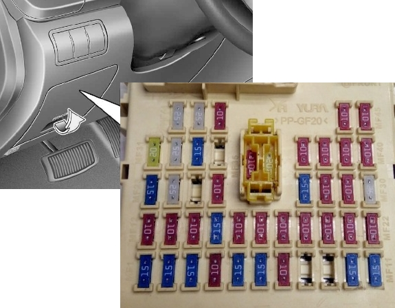
Fuses
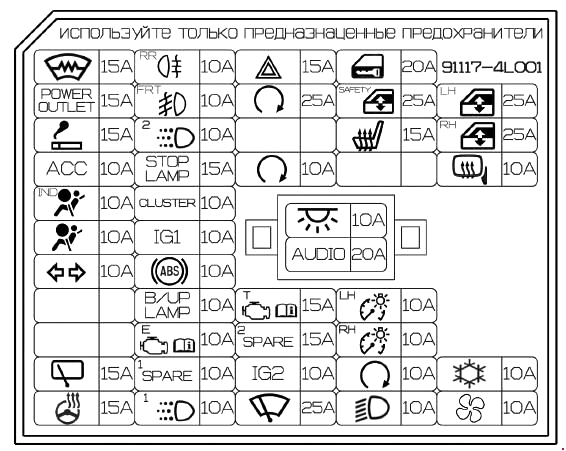
Example of a circuit from the block cover
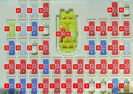
Fuse description
| 1 | 15A FRT-Deicer – Windshield Defroster |
| 2 | 15A P/OUTLET – 12V socket |
| 3 | 10A C/LIGHTER – Cigarette lighter |
| 4 | 10A ACC – Ignition switch – audio system, body electrical equipment control module, automatic transmission lock control module, electronic key system control unit |
| 5 | 10A A/BAG IND – Airbag Off Indicator – Front |
| 6 | 10A A/BAG – Airbags, SRS control module |
| 7 | 10A T/SIG Emergency light alarm |
| 8 | Reserve |
| 9 | Reserve |
| 10 | 15A R/WPR – Rear window wiper – motor, Multifunction switch |
| 11 | Reserve |
| 12 | 10A RR (R/FOG) – Fog lights (rear) |
| 13 | 10A FRT (F/FOG) – Fog lights (front) |
| 14 | 10A ROOM 2 – Battery saver relay (automatic protective shutdown) |
| 15 | 15A STOP LP – Stop signals |
| 16 | 10A CLUSTER – Instrument cluster |
| 17 | 10A IG1 1 – Security system control module |
| 18 | 10A ABS – hydroelectronic ABS module |
| 19 | 10A B/UP LP – Rear running lights (switch) |
| 20 | 10A PCU – control module, body electrical equipment control module, automatic transmission lock control module, electronic key system control unit |
| 21 | 10A H/LP LH – Headlight – left |
| 22 | 10A DAY TIME RUNNING LIGHT – Daytime running lights |
| 23 | 15A HAZARD – Hazard warning switch |
| 24 | 25A SMK 1 – Control module, body electrical equipment control module, automatic transmission lock control module, electronic key control unit |
| 25 | Reserve |
| 26 | 10A SMK 2 – Control module, body electrical equipment control module, automatic transmission lock control module, electronic key control unit, engine start and stop button switch |
| 27 | 15A TCU – speed sensor Automatic transmission range sensor. Pulse generator |
| 28 | 15A IGN COIL – Ignition coil 1-4, capacitor |
| 29 | 10A IGN 2 – Power windows. Sunroof |
| 30 | 25A F/WPR – Windshield Wiper |
| 31 | 20A DOOR LOCK – Central locking – control unit |
| 32 | 25A SAFETY P/WDW – Power windows – locking |
| 33 | 15A S/HEATER – Front seat heating |
| 34 | Reserve |
| 35 | 10A ROOM 1 – Interior lighting. Air conditioning |
| 36 | 20A AUDIO – Audio system |
| 37 | 10A TAIL LH – Headlight and lamp on the left side. License plate light |
| 38 | 10A TAIL RH – Headlight and lamp on the starboard side. Illumination of switches, switches in the cabin, selector lever. Instrument cluster, power and shift buttons |
| 39 | 10A START – Starter – relay. Anti-theft alarm |
| 40 | 10A H/LP RH – Headlight – right |
| 41 | 25A P/WDW LH – Power window control unit – left rear switch |
| 42 | 25A P/WDW RH – Power window control unit – right rear switch |
| 43 | 10A HTD MIRR – Heated exterior rear-view mirror system |
| 44 | 10A A/CON 2 – Air conditioner |
| 45 | Reserve |
Fuse number 3 at 10A is responsible for the front cigarette lighter, and fuse number 2 at 15A is responsible for the additional sockets.
To learn more about how to replace the cigarette lighter fuse in a 1st generation Hyundai Solaris, you can watch this video.
Relay
There may be some relays on the back of the unit.
Scheme
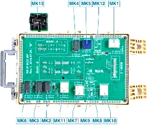
Relay decoding
- MK1 Rear window heating relay
- MK2 Fog light relay
- MK3 Fog light relay
- MK4 Parking light relay
- MK5 Interior lighting relay
- MK6 Windshield heating relay
- MK7 Central locking relay
- MK8 Reserve
- MK9 Reserve
- MK10 Alarm relay
- MK11 Power window relay
- MK12 Reserve
- MK13 Electronic control relay for braking signals (installed outside the unit)
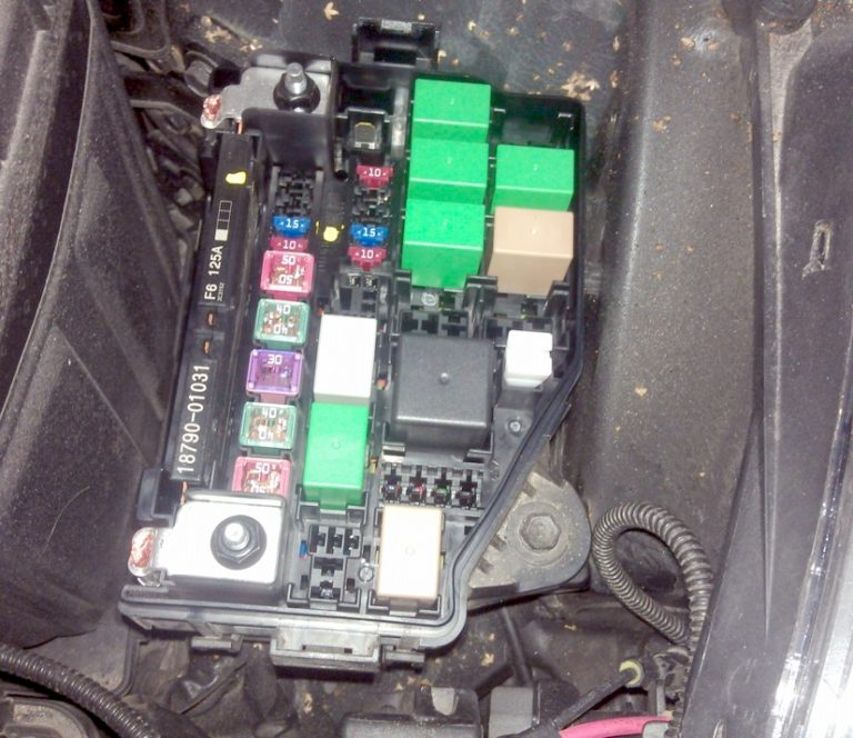
Block under the hood
It is located on the right side of the engine compartment next to the battery.
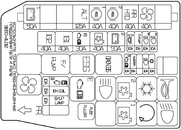
Purpose of fuses
| 1 | Reserve |
| 2 | Reserve |
| 3 | 15A F/PUMP – Fuel pump |
| 4 | 10A HORN – Sound signal |
| 5 | 50A B+2 – Switch unit: hazard warning light, power windows, central locking, fuses – F23-F25, F31, F32 |
| 6 | 40A C/FUN – Heating system control unit |
| 7 | 40A ECU 1 – Engine Control Unit – Relay 1. Fuse F25 |
| 8 | 40A IG1 – Ignition switch, body electrical control module, automatic transmission lock control module, start-stop button control unit. |
| 9 | 50A IG2 – Ignition switch, body electrical control module, automatic transmission lock control module, start-stop button control unit |
| 10 | 10A A/CON – Air conditioning |
| 11 | Reserve |
| 12 | Reserve |
| 13 | 15A INJECTOR – Engine Control Module. Transmission Control Module. Fuel Pump – Relay. Oil Control Valve |
| 14 | 10A SENSOR – Engine control module. Camshaft sensor. Oxygen sensor. Immobilizer. Air conditioner – relay. Fan – low speed relay and high speed relay. Solenoid valve |
| 15 | 10A ECU 2 – Electronic Engine Control Unit |
| 16 | Reserve |
| 17 | 10A B/UP LP – Transmission control unit. Automatic transmission sensor. Instrument panel. Rear combination lamps. |
| 18 | 10A WAPER – Glass cleaner |
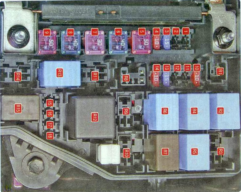
Relay designation
| R1 | Reserve |
| R2 | Horn relay |
| R3 | Ignition switch relay, body electrical control module, automatic transmission lock control module, engine start/stop button control unit |
| R4 | Air conditioner relay |
| R5 | Ignition lock switch relay |
| R6 | Fan relay (low speed) |
| R7 | Fan relay (high speed) |
| R8 | Diagnostic connector relay |
| R9 | Ignition switch relay |
| R10 | Ignition switch relay, body electrical control module, automatic transmission lock control module, engine start/stop button control unit |
| R11 | Emergency braking warning relay |
| R12 | Electronic engine control unit relay |
| R13 | Fuel pump relay |
| R14 | Reserve |
| R15 | Cooling system radiator fan relay |
Power fuse block
It is attached to the side of the main unit and consists of high-power fuse links.
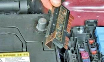
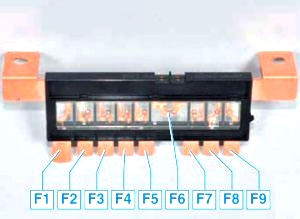
Description
- 50A Taillight relay
- Reserve
- Reserve
- 125A Generator
- 40A ABS hydro-electronic module, diagnostic connector
- 40A Hydroelectronic ABS module
- 40A Rear window heating relay
- 40A Fan Relay
- Reserve