Toyota Aristo 1 generation was produced in 1991, 1992, 1993, 1994, 1995, 1996 and 1997. During this time, the model was restyled. The most popular models were in the 147 and 141 bodies. Lexus GS 300 with left-hand drive is made on the general base of Toyota Aristo 1. These cars have similar electrical circuits. In our publication, you will find information on the location of electronic control units, a description of fuses and relays Toyota Aristo 147 (Lexus gs300) with block diagrams and photo examples of their implementation. We will highlight the cigarette lighter fuse. In conclusion, we offer complete electrical circuits for download.
Blocks in the cabin
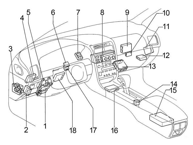
Location
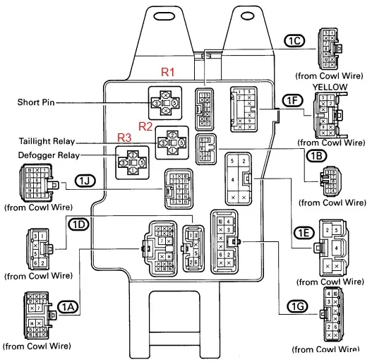
Block layout diagram
- Integrated relay
- Daytime running lights relay
- Relay block
- Anti-theft system control unit
- Fuse box
- Windscreen wiper relay
- Distribution block
- Air conditioning control unit
- Traction control unit
- Air conditioner booster
- Anti-lock braking system and traction control system control unit
- Heater relay
- Engine Control Unit (M/T) / Engine and Automatic Transmission Control Unit (A/T)
- Gear selector lock control unit
- Central airbag unit
- Cruise control unit
- PPS Block
- Steering Column Control Unit
Fuse box
It is located at the bottom of the instrument panel on the steering side, behind the protective cover.
Option 1
Scheme
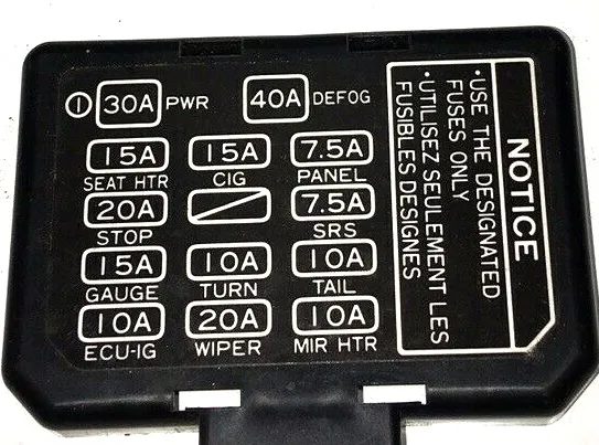
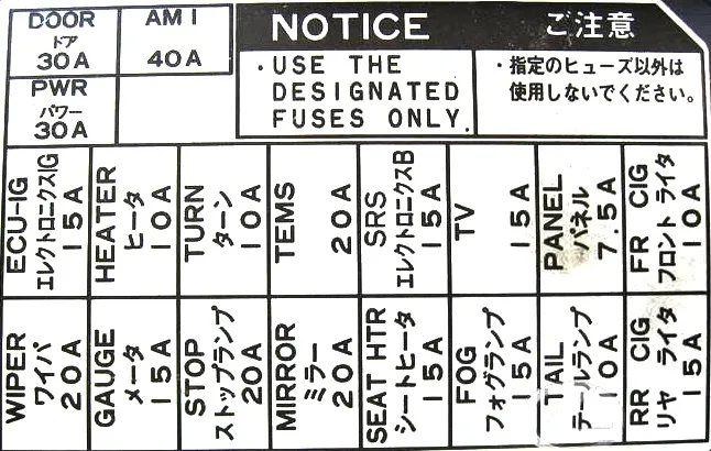
Designation
| SEAT HTR | Heated seats |
| STOP | Brake lights, additional brake light, gear selector lock, ABS, TRC, multi-port fuel injection system/sequential multi-port fuel injection system |
| GAUGE | Instrument cluster, reversing lights, heated rear window, heated mirrors, heater control unit, air conditioning, service indicators, warning buzzer, charging system, automatic transmission indicators, daytime running lights |
| ECU-IG | Gear selector lock, telephone, central locking, seat belts, ABS, TRC, power steering, cruise control, tilt and height steering column adjustment, antenna, cooling fan, instrument panel lighting, automatic lighting system, gear selector |
| CIG | Cigarette lighter (front/rear), clock, air conditioning, audio system, gear selector lock, SRS airbag system, central locking, electric mirrors, antenna, anti-theft system |
| – | – |
| TURN | Direction indicators |
| WIPER | Windscreen wiper and washer, headlight cleaners |
| PANEL | Automatic transmission indicators, heater control unit, hazard warning lights, glove compartment light, ashtray light, clock, cigarette lighter light, audio system, gear selector, instrument panel light, daytime running lights |
| SRS | SRS airbag system |
| TAIL | Side lights, number plate lights |
| MIR HTR | Heated mirrors |
| POWER | Power windows, sunroof, electric seats, central locking, steering column adjustment, power relay (POWER) |
| DEFOG | Rear window heating, fuse: “MIR HTR” |
| DOOR | Doors, central locking. |
The fuse marked CIG is responsible for the cigarette lighter.
Relay
Relays can be attached to the back side of the block.
Scheme
| R1 | Jumper (Short pin) |
| R2 | Side light |
| R3 | Rear window heating |
Relay block
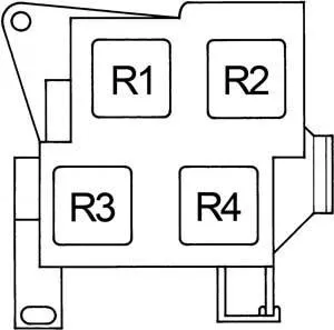
| R1 | Direction indicators (hazard warning lights) |
| R2 | Daytime running lights #4 |
| R3 | Fog light |
| R4 | Power relay (window lifters, sunroof, central locking, steering column, electric seats) |
Additional elements
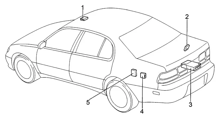
- Hatch relay
- Door lock control unit
- Audio amplifier
- Antenna relay
- Fuel pump control unit
Blocks under the hood
Location
Block layout diagram
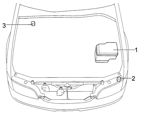
- Fuse and relay box
- Headlight Washer Relay
- Traction control relay
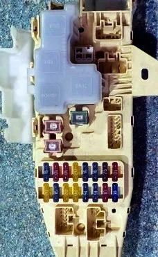
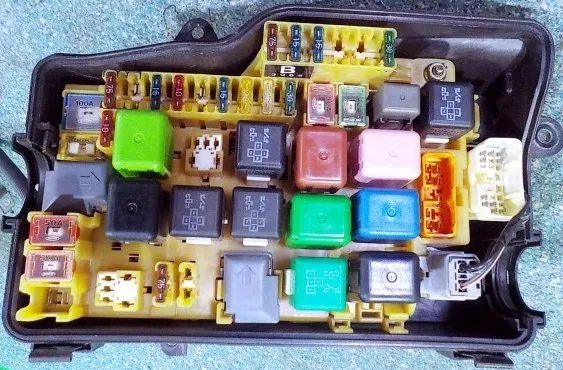
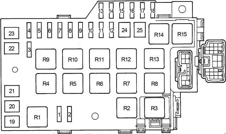
Fuse and relay box
Photo example
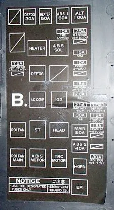
| 1 | 15A FOG – Fog light |
| 2 | 7.5A DRL – Daytime Running Lights |
| 3 | 10A TRAC – Traction Control |
| 4 | 10A DOME – Interior lighting, sunroof, cruise control, door open indicator, personal lighting, luggage compartment lighting, door lighting, footwell lighting, ignition switch lighting, ABS clock, antenna, audio system, anti-theft system, wireless remote control system |
| 5 | 7.5A ECU-B – Wireless Remote Control System, ABS, TRC, Cruise Control, Daytime Running Lights, Air Conditioning |
| 6 | 7.5A ALT SENSING – Charging System |
| 7 | 15A AM2 – Multiport fuel injection system/sequential multiport fuel injection system, SRS airbag system, battery charge indicator, ignition system, instrument cluster, service indicators, warning buzzer |
| 8 | 15A TEL – Telephone |
| 9 | 20A HAZ. HORN – Emergency alarm, sound signal |
| 10 | 20A EFI – Automatic Transmission Control Module, Multiport Fuel Injection System/Sequential Multiport Fuel Injection System |
| 11 | 25A RADIO NO. 1 – Audio system, antenna |
| 12 | 30A IG2 – Ignition System |
| 13 | 7.5A OBD II – 1996-1997: Diagnostic Connector |
| 14 | 15A HEAD RH – Right headlight |
| 10A HEAD RH-UPR – High Right Beam | |
| 15 | 15A HEAD LH – Left headlight |
| 10A HEAD LH-UPR – Left High Beam | |
| 16 | 10A HEAD RH-LWR – Low beam right |
| 17 | 10A HEAD LH-LWR – Low beam left |
| 18 | 30A RDI FAN – Cooling system fan |
| 19 | – |
| 20 | 40A AM1 – Ignition switch, fuses: “ECU–IG”, “WIPER”, “GAUGE”, “TURN”, “SEAT–HTR”, “CIG” |
| 21 | 50A HEATER – Heater relay |
| 22 | 60A ABS – Cooling Fan Main Relay, Traction Control Relay, Anti-Lock Brake System Relay, Fuses: “TRAC” |
| 23 | 100A ALT – Parking light relay, generator, fuses: “FOG”, “AM1”, “HEATER”, “DEFOG”, “ABS”, “STOP”, “SRS”, “POWER” |
| 24 | 50A MAIN – Headlight relay, daytime running light relay #2, starter relay |
| 25 | 40A ABS No.2 – Anti-slip motor, Anti-lock brake system motor |
| Relay | |
| R1 | Daytime running lights #3 |
| R2 | Cooling system fan |
| R3 | Daytime running lights #2 |
| R4 | Heater |
| R5 | Jumper (Short pin) |
| R6 | Air conditioning compressor clutch |
| R7 | Starter |
| R8 | ABS motor |
| R9 | ABS |
| R10 | Main cooling system fan |
| R11 | Ignition (IG2) |
| R12 | Headlights |
| R13 | Anti-slip system |
| R14 | Sound signal |
| R15 | Engine Control Unit (EFI) |