Volkswagen Tiguan – a compact crossover produced in 2 generations from 2007 to the present. The first generation Volkswagen Tiguan was produced in 2008, 2009, 2010, 2011, 2012, 2013, 2014, 2015 and 2016. During this period, it underwent restyling once. In this article you will find a description of the fuse blocks and relays in the Volkswagen Tiguan with their photos – examples and diagrams. We will separately highlight the fuse responsible for the cigarette lighter.
Block arrangement
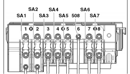
Scheme
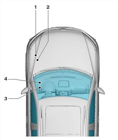
Transcript
- Main fuse block in the communication unit
- Fuse switch block.
- Fuse box in the passenger compartment.
- Relay block.
The actual purpose of the fuse box depends on the year of manufacture and the vehicle’s equipment level.
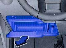
Fuse block
It is located in the passenger compartment, at the bottom of the instrument panel on the driver’s side, behind a protective cover.
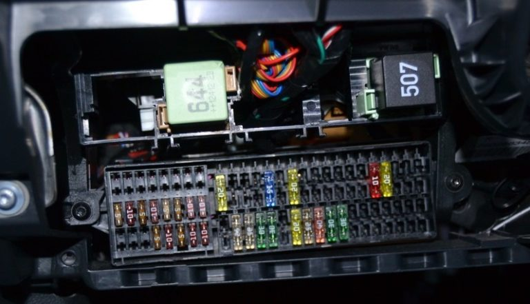
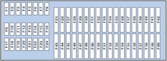
Description
| 1 | Not used |
| 2 | Not used |
| 3 | Not used |
| 4 | Not used |
| 5 | Not used |
| 6 | Not used |
| 7 | Not used |
| 8 | Not used |
| 9 | 5A Airbag control unit, Front passenger airbag off indicator lamp |
| 10 | 10A All-wheel drive system control unit |
| 11 | 5A Parking autopilot or assistant control unit |
| 12 | 10A Left headlight gas discharge lamp control unit |
| 13 | 5A High pressure sensor, Electrochromic interior rear-view mirror, Reversing light switch, Washer jet heating resistor, AUTO HOLD button, AUTO HOLD function indicator lamp, Seat occupancy detection system control unit, Front camera of auxiliary water systems, ASR and ESP off button, Motion control program button |
| 14 | 10A Power steering control unit, Vehicle position monitoring system control unit, Starter relay, Electronic damping control unit, Trailer recognition control unit, Tiptronic switch, Data bus diagnostic interface, Instrument cluster control unit, Heater control unit, Light switch, Engine control unit, ABS control unit |
| 15 | 10A Relay for operation in autonomous heater mode, Voltage converter, Adaptive lighting and headlight range control unit, Air flow meter, Diagnostic connector, Electromechanical parking brake control unit, Switch and instrument cluster backlight brightness regulator, Left headlight range control crankcase ventilation system heating resistor, Right headlight range control actuator motor |
| 16 | 10A Right headlight gas discharge lamp control unit |
| 17 | 5A Instrument cluster control unit |
| 18 | 5A Mobile phone control electronics control unit, Multimedia system control unit, Magnetic field sensor for compass |
| 19 | 7.5A Steering column control unit |
| 20 | 5/7.5A Tire pressure monitoring control unit, Additional liquid heater radio signal receiver, Rear window heating relay, Two-tone sound signal relay, ABS control unit, Tiptronic switch, Automatic transmission control unit, Air conditioning control unit, Climatronic control unit, Heater control unit |
| 21 | 7.5/15A On-board network control unit, Front passenger door control unit, Right rear door control unit |
| 22 | 5A On-board network control unit, Alarm siren, Interior security system sensor |
| 23 | 10A Rain and light sensor, Light switch, Vehicle position tracking system control unit, Access and engine start authorization system control unit, Rear view camera control unit, Magnetic field sensor for compass, Electromechanical parking brake button, Diagnostic connector |
| 24 | 10A Driver’s door control unit, Left rear door control unit |
| 25 | 5/20A Multifunction switch, Automatic transmission control unit, DSG gearbox Mechatronic unit |
| 26 | Not used |
| 27 | Not used |
| 28 | 40A Relay for operation in autonomous heater mode, Heater control unit, Air conditioning control unit |
| 29 | 15A Rear window wiper motor |
| 30 | Not used |
| 31 | 20A Cigarette Lighter and 12V Socket |
| 32 | Not used |
| 33 | Not used |
| 34 | Not used |
| 35 | Not used |
| 36 | Not used |
| 37 | Not used |
| 38 | 10A Electronic steering column lock control unit |
| 39 | 20A Headlight cleaning system relay |
| 39 | 15A Trailer recognition control unit/preparation for installation of TSU |
| 40 | 15A Trailer recognition control unit |
| 41 | 15A Trailer recognition control unit |
| 42 | 20A Trailer recognition control unit |
| 43 | 25A Sliding sunroof control unit |
| 44 | 25A Electromechanical parking brake control unit |
| 45 | 25A Supply fan relay, Rear window heating relay |
| 46 | 30A Driver’s door control unit, Left rear door control unit |
| 47 | 30A Front passenger door control unit, Right rear door control unit |
| 48 | 20A Fuel pump relay |
| 49 | 20A On-board network control unit |
| 50 | 25A Electromechanical parking brake control unit |
| 51 | 40A Supply fan control unit |
| 52 | 20/30A Front seat heating control unit |
| 53 | 20/30A Headlight cleaning system relay |
| 54 | 30A Inverter with socket, 12 V – 230 V |
| 55 | 15A Driver’s seat lumbar support adjustment switch |
| 56 | 15A Electronic damping control system control unit |
| 57 | 25A Sunroof blind control unit |
| 58 | 1A Towbar warning light (locked) |
| 59 | Control unit with radio navigation system display |
| 60 | Not used |
Fuse number 31 at 20A is responsible for the cigarette lighter in the 1st generation Volkswagen Tiguan.
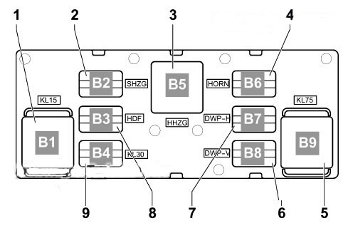
Relay block
The relay block is located on the back of the fuse block.
Relay purpose
- Terminal 15 power relay 2, -J681-, (460) Slot B1
- Exterior mirror heating relay -J99- (449) Slot B2
- Rear window heating relay -J9- (53) Slot B5
- Two-tone horn relay -J4- (449) Slot B6
- Contact relief relay X-J59-(460) Slot B9
- Dual washer pump relay 2 -J730- (404) Slot B8
- Dual washer pump relay 1 -J729- (404) Slot B7
- Reserve Slot B3
- Power relay 2 terminals 30 -J689- (449) Slot B4
Scheme
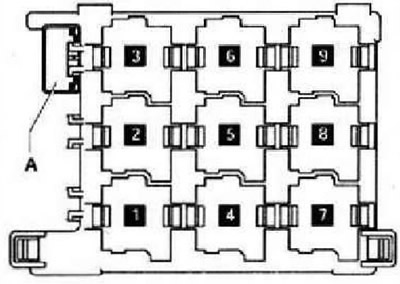
Transcript
- Auxiliary heater relay
- Starter relay
- –
- Heater fan relay
- Alarm system relay / headlight washer pump relay
- Fuel pump relay (FP)
- Engine coolant heater relay 1
- Engine Coolant Pump Relay – Some Models, Fuel Pump (FP) Relay – Some Models, Parking Heater Fuel Pump Relay – Some Models
- Engine coolant heater relay 2
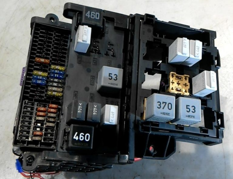
Communication unit under the hood
It consists of a fuse and relay compartment (Main compartment – 1) and high-power fuses (main fuses – 2) and is located next to the battery, under a protective cover.
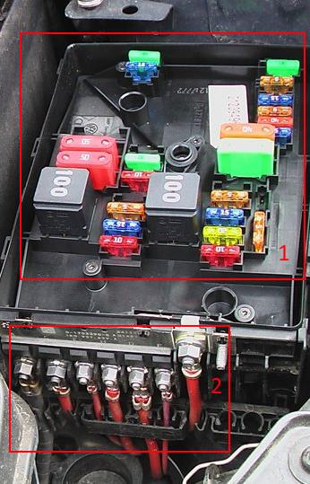
Main fuse compartment
Option 1
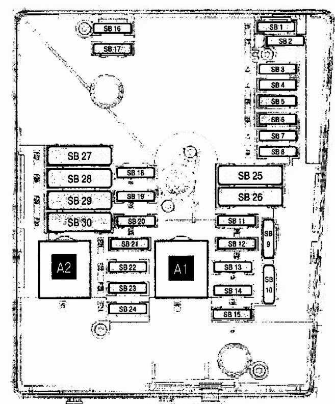
Marking
| 1 | |
| 2 | |
| 3 | 5A On-board network control unit |
| 4 | 30A ABS control unit, ABS hydraulic unit |
| 5 | |
| 6 | 5A Instrument cluster control unit, Steering column control unit |
| 7 | 40A Relay 2 power supply terminal 15 |
| 8 | 25A Control unit with radio navigation system display, Head unit, TV tuner, Digital satellite radio tuner, Multimedia system control unit, Voltage converter |
| 9 | 5A Mobile phone control electronics control unit |
| 10 | 5/10A Power Relay, Engine Control Unit |
| 11 | 20A Auxiliary heater control unit |
| 12 | 5A Diagnostic data bus interface |
| 13 | 15/30A Engine control unit |
| 14 | 5A Fuel pressure regulator, Fuel metering valve, Ignition coils |
| 15 | 5/10/15A Solenoid clutch of the drive supercharger, Lambda probe heating element, Lambda probe heating element 1 after the catalyst, Fuel system diagnostic pump, Fuel pump relay, Glow plug control unit, Electric fuel pump relay 2 |
| 16 | 30A On-board network control unit |
| 17 | 15A Alarm siren relay |
| 18 | 30A Digital Audio Amplifier |
| 19 | 30A Wiper motor control unit |
| 20 | 10A Fuel pressure regulator, Coolant circulation pump |
| 21 | 10/20A Lambda sensor heating element, Fuel pump control unit |
| 22 | 5A Clutch pedal position sensor |
| 23 | 10A Boost pressure limit solenoid valve, EGR radiator switching valve, Fuel pressure regulator, Air flow meter |
| 24 | 10A Radiator fan control unit, Heating relay, Additional cooling system pump relay, Power relay, Boost pressure limit solenoid valve, Adsorber solenoid valve 1, Valve 1 of the gas distribution phase change system, Charge air recirculation valve, Intake manifold flap valve, Coolant pump 2, Coolant circulation pump, Fuel pump relay |
| 25 | 40A ABS control unit |
| 26 | 30A On-board network control unit |
| 27 | Not used |
| 28 | 50A Glow plug control unit |
| 29 | 50A Thermal fuse 1 driver’s seat adjustment, Fuses 54 – 57 in the passenger compartment |
| 30 | 50A Contact Unloading Relay X |
- A1 – Main ignition circuit relay (diesel)
- A2 – Engine Control Relay (EC) (diesel)
Option 2
Photo – diagram
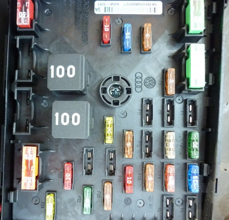
Appointment
| 1 | 15A Mechatronic unit DSG gearbox |
| 2 | 30A ABS control unit |
| 3 | 15A Horn Relay |
| 4 | Reserve |
| 5 | 5A On-board network control unit |
| 6 | Reserve |
| 7 | 25A Voltage converter, Control unit with radio navigation system display, Multimedia system control unit |
| 8 | 40A Relay 2 power supply terminal 15 |
| 9 | Reserve |
| 10 | 5/10A Lambda probe heating element, Supercharger drive electromagnetic clutch, Fuel system diagnostic pump, Glow plug control unit |
| 11 | 5A Instrument cluster control unit, Steering column control unit |
| 12 | 5A Mobile phone control electronics control unit |
| 13 | 5/10A Engine control unit |
| 14 | 15/30A Engine control unit |
| 15 | 5A Diagnostic data bus interface |
| 16 | 10A Boost pressure limit solenoid valve, Recirculation system radiator switch, Air flow meter, Fuel pressure regulator |
| 17 | 10/15A Fuel pressure control valve, Coolant circulation pump |
| 18 | 10A Lambda sensor heating element 20A Fuel pump control unit |
| 19 | 30A Digital Audio Amplifier |
| 20 | 5A Clutch pedal position sensor |
| 21 | 30A Auxiliary heater control unit |
| 22 | 30A Wiper motor control unit |
| 23 | 10A High-power heating relay, Low-power heating relay, Fuel pump relay, Coolant circulation pump 2, Radiator fan control unit, Electric fuel pump relay 2, Boost pressure limit solenoid valve, Charge air recirculation valve, Variable valve timing system adsorber solenoid valve 1, Intake manifold flap valve, Motronic power relay 2, Brake light switch |
| 24 | 20A Ignition coils 15A Fuel metering valve |
| 25 | 30A On-board network control unit |
| 26 | 30A On-board network control unit |
| 27 | 50A Contact Unloading Relay X |
| 28 | 50A Glow plug control unit |
| 29 | 50A Thermal fuse 1 driver’s seat adjustment, Fuses 54 – 57 in the passenger compartment |
| 30 | 40A ABS Control Unit (Pump) |
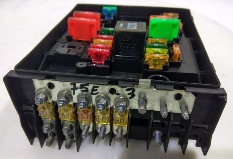
Main fuse section
Scheme
Description
- 200A – Generator
- 80A – Power steering control unit
- 50A – Fuse 40 in the fuse box
- 50A – Radiator fan control unit
- 80A – Fuse block
- 70A – Radiator fan control unit, High power heating relay
- Reserve
- 40A – Low power heating relay