Renault Logan 1st generation was produced in 2005, 2006, 2007, 2008, 2009, 2010, 2011, 2012 and 2013 with petrol engines 1.4 and 1.6 and diesel 1.5 liters. Also known as Dacia Logan 1. In this publication you will find a description of fuses and relays Renault Logan 1 with block diagrams and their locations. Note the cigarette lighter fuse.
The number of fuses and relays in the blocks, as well as their purpose, may differ from that shown and depends on the year of manufacture and the level of equipment of your Renault Logan 1.
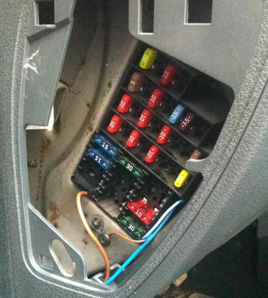
Block in the cabin
The main unit is located at the left end of the instrument panel under a plastic cover.
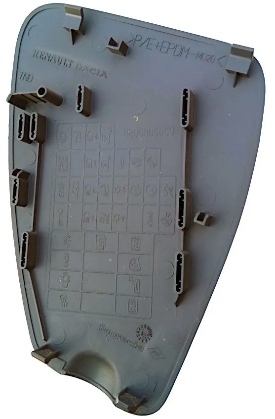
On the reverse side of which there will be the current designation of fuses for your Renault Logan 1.
Example
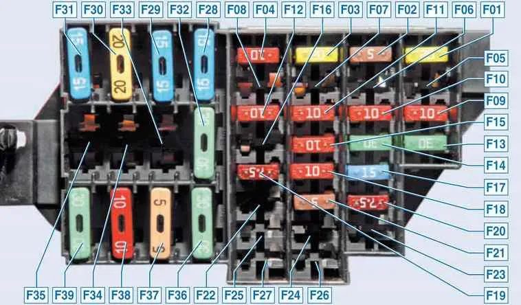
F01 20A — windscreen wiper, rear window heating relay coil
If the windshield wipers stop working, check the condition of the steering column switch, its tracks, contacts and connector, as well as the motor, its brushes and the wiper mechanism trapezium. If you hear a click when you turn on the switch, the problem is often moisture and water getting inside the gear motor.
F02 5A — instrument panel, windings of relay K5 of fuel pump and ignition coil, engine control system from ignition switch (ECU)
F0З 20А — brake light bulbs, reversing light, windshield washer
If none of the brake lights are on, first check the limit switch, which is located in the pedal assembly and responds to pressing the brake pedal, as well as its connector. Check the serviceability of all the lamps, they could have burned out one by one, as well as the contacts in the sockets.
F04 10A — airbag control unit, turn signal lamps, diagnostic connector, immobilizer
If the turn signals do not work, check the condition of the lamps and the absence of a short circuit in their connectors, the steering column switch and its contacts. Also, the turn signals may not work correctly if there is a short circuit in other lighting devices.
F05 – F08 – Free
F09 10A — low beam in the left headlight, low beam switch lamp on the panel, headlight washer pump
F10 10A – low beam in the right headlight
F11 10A – left headlight, high beam, high beam indicator lamp on the instrument panel
F12 10A – right headlight, high beam
If the headlights no longer shine with high beams in the appropriate mode, check the bulbs, steering column switch with connector and wiring.
F13 30A – rear electric windows .
F14 30A – front electric windows .
F15 10A — ABS
F16 15A — Heated front seats
If the front seats stop heating up when you turn on their heating, the problem may be in the wiring or in the power button. There is also a thermal switch inside the seat, which does not allow the seats to heat up and breaks the circuit above a certain temperature.
F17 15A – Sound signal
F18 10A — Left headlamp side light bulbs; left rear light side light bulbs; number plate light bulbs; instrument cluster and control illumination on the instrument panel, console and floor tunnel trim; switch unit buzzer
F19 7.5A — Right headlight side light bulbs; right rear light side light bulbs; glove compartment light bulbs
F20 7.5A — Rear fog light indicator and lamps
F21 5A — Heated side mirrors
F22 – Reserve
F23 – Backup, alarm
F24 – Reserve
F25 – Reserve
F26 – Reserve
F27 – Reserve
F28 15A — Interior and trunk light lamps; constant power supply for the audio head unit
If the light does not come on when you open any of the front doors, check its limit switch and wiring, as well as the position of the light switch (Auto). Another problem may be in the connector, which is located in the left middle pillar of the body, where the driver’s belt is. To get to it, you need to remove the cover. If the light does not come on when you open the rear doors, check the wiring from the limit switches under the rear seat.
F29 15A — General power supply (hazard warning switch; direction indicator switch; intermittent windscreen wiper; central lock control; engine management system diagnostic connector)
F30 20A – Door and trunk lock, central bell
F31 15A — Circuit of winding of relay K8 of fog lights
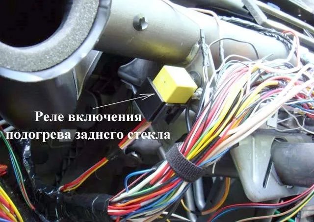
F32 30A — Rear window heating
If the heating does not work, first check the contacts and voltage at the terminals along the edges of the glass. If voltage reaches the heating elements, check the rear window for broken elements. If voltage does not reach, the wire running from the switch on the front panel to the rear window may have frayed, ring it. The relay, which is located under the dashboard on the left, may also be out of order; to access it, you need to remove the casing. Also check the heating button on the panel
F33 – Reserve
F34 – Reserve
F35 – Reserve
F36 30A — Air conditioner, heater
If your air conditioner does not work, also check fuse F07 and relay K4 under the hood. If there are problems, the system most likely has run out of freon and needs to be refilled or the leak eliminated. Fuse F39 is also responsible for heating.
F37 5A — Electric mirrors
F38 10A — Cigarette lighter; power supply to the head unit of the audio reproduction from the ignition switch
F39 30A — Heater fan relay K1 winding circuit; climate control panel
Fuse number 38 for 10A is responsible for the cigarette lighter.
Let us also remind you that some elements can be installed outside this block!
Block under the hood
In the engine compartment of the Renault Logan 1st generation, there are two different options for the arrangement of elements. In both of them, the main blocks are on the left side, next to the battery.
Option 1
Photo – diagram
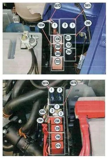
| 597A – F1 | 60A Security Alarm, Outdoor Lighting Switch, Daytime Running Light Relay (Unit 1034) |
| 597A – F2 | 60A Exterior Light Switch, Passenger Compartment Fuse Box |
| 597B – F1 | 30A Relay Board Power Supply |
| 597B – F2 | 25A Injection system relay power supply circuit |
| 597B – F3 | 5A Power supply circuit of the injection system relay, injection system ECU |
| 597C – F1 | 50A ABS ECU |
| 597C – F2 | 25A ABS ECU |
| 597D – F1 | 40A High speed electric fan relay (relay 236), relay board |
| 299 – 231 | 20A Fog lights |
| 299 – 753 | 20A Headlight Washer Pump |
| 784 – 474 | 20A Air Conditioning Compressor Relay |
| 784 – 700 | 20A Low speed relay for electric fan |
| 1034 – 288 | 20A Daytime Running Light Relay |
| 1034 – 289 | 20A Daytime Running Light Relay |
| 1034 – 290 | 20A Daytime Running Light Relay |
| 1047 – 236 | 20A Fuel Pump Relay |
| 1047 – 238 | 20A Injection Lock Relay |
| 233 | 40A Heater Fan Relay |
| 236 | 40A High Speed Electric Fan Relay |
Option 2
Scheme
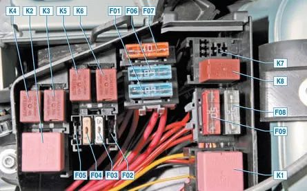
| F01 | 60A Circuits: power supply for the ignition switch and all consumers powered by the switch; external lighting switch |
| F02 | 30A Power circuit of the K3 relay of the cooling system fan (on a car without air conditioning) |
| F03 | 25A Power circuits: relay K5 of the fuel pump and ignition coil; main relay K6 of the engine management system |
| F04 | 5A Circuits: constant power supply of the engine management system ECU; windings of the main relay K6 of the engine management system |
| F05 | 15A Reserve |
| F06 | 60A Passenger compartment fuse box power supply circuit |
| F07 | 40A Power circuits: relay K4 air conditioner; relay K3 low speed cooling fan (on a car with air conditioning); relay K2 high speed cooling fan (on a car with air conditioning) |
| F08F09 | 25/50A ABS ECU Circuits |
- K1 — heater fan relay, heater fan motor. See information about F36.
- K2 — high-speed cooling fan relay (for cars with air conditioning), radiator cooling fan electric motor.
- KZ — low-speed cooling fan relay (for cars with air conditioning) or radiator cooling fan relay (for cars without air conditioning), cooling fan electric motor (for cars with air conditioning — via a resistor).
- K4 — air conditioner relay, compressor electromagnetic clutch. See information about F36.
- K5 — fuel pump and ignition coil relay.
- K6 — main relay of the engine management system, oxygen concentration sensor, speed sensor, fuel injectors, solenoid valve for purging the adsorber, windings of relays K2, K3, K4.
- K7 — headlight washer pump relay.
- K8 — fog lamp relay. See information about F31.