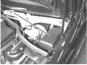
Mercedes w220 represents the fourth generation of Mercedes-Benz S-class cars, which was produced in 1998, 1999, 2000, 2001, 2002, 2003, 2004, 2005 in various trim levels S280, S320 , S350, S350 AMG, S65, AMG, S320 CDI, S400 CDI. During this time, the model has undergone restyling. In our article you will find a description of the fuses and relays of the Mercedes 220 with block diagrams, photo examples and their locations. We will note the cigarette lighter fuse and show how to check the power supply to the air suspension compressor.

The design of the blocks and the purpose of their elements may differ from the one presented and depends on the year of manufacture, equipment level and delivery region of your vehicle.
Blocks under the hood
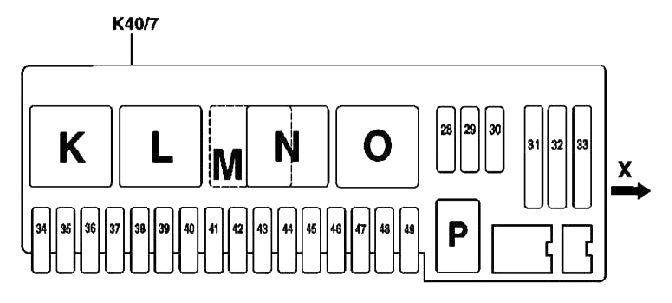
Block on the left side
One fuse and relay block is located on the left side of the engine compartment.
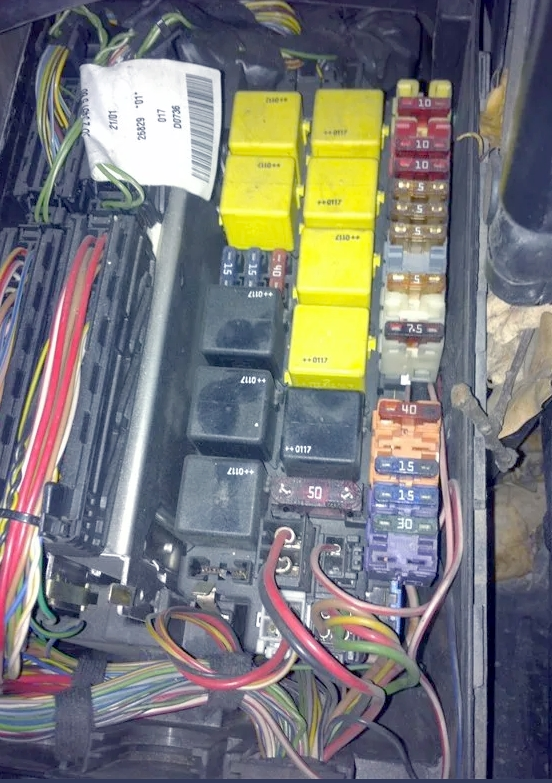
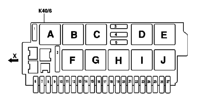
Description
Fuses
| № | Current | Description |
|---|---|---|
| 1 | 40A | Wiper blade heating relay (K40/6kA) |
| 2 | 50A | Relay for injection and evacuation pumps (K40/6kF) |
| 3 | 15A | Horizontal adjustment of the steering column position:• Steering column longitudinal adjustment relay 1 (K40/6kD)• Steering column longitudinal adjustment relay 2 (K40/6kE) |
| 4 | 15A | Vertical adjustment of the steering column position:• Steering column tilt angle adjustment relay 1 (K40/6kI)• Steering column tilt angle adjustment relay 2 (K40/6kJ) |
| 5 | 40A | Wiper ON/OFF relay (K40/6kH) |
| 6 | 7.5A | Auxiliary heater switch (S4/3) / (from 09.2002 – absent) |
| 7 | – | |
| 8 | – | |
| 9 | 30A | If air suspension is available:• Airmatic system control unit with ADS (N51)with active body clearance control (ABC) system:• ABC system control unit (N51/2) |
| 10 | 15A | Windshield washer pump (M5/1) |
| 11 | 15A | Cigarette lighter with front ashtray illumination (R3) |
| 11 | 5A | (from 09.2002 – VISC power supply separation point X137/1) (from 09.2002 – only on models for Japan) |
| 12 | 7.5A | Dynamic seat belt webbing lock (A60) / (from 09.2002 – absent) |
| 13 | 40A | Front left door control unit (N69/1) |
| 14 | – | |
| 15 | – | |
| 16 | 7.5A | Brake light switch (S9/1) |
| 17 | – | |
| 18 | 5A | If you have a GSM (D2B) mobile phone (basic equipment) (code 317):• mobile phone plug connector (X39/39)If you have an MB GSM (D2B) phone (code 316):• D2B interface for landline telephone (A59)If you have an MB GSM (D2B) phone (code 316) with the Tele Aid emergency call system (code 347):• Tele Aid system control unit (A35/8)If you have an MB GSM (D2B) telephone (code 316) with the E-Call emergency call system (code 349) via the cable connector of terminal 15R (Z3/12):• D2B interface for landline telephone (A59)• range switching control unit (N96)• E-Call system control unit (A35/8) (from 09.2002 – If there is an MB GSM (D2B) phone (code 854):• via connector 15R(Z3/1) of circuit 2: – frequency selection control unit (N96) – E-Call control unit (A35/8) – D2B interface for mobile phone (A59/1) |
| 19 | 5A | from 09.2002 – front left (A76) and right (A76/1) reversible emergency tensioners |
| 20 | 5A | Dashboard (A1) Diagnostic connector (X11/4) / (from 09.2002 – absent) |
| 21 | 5A | Dashboard (A1) / (from 09.2002 – absent) |
| 22 | 5/1A | Dashboard (A1) / (from 09.2002 – Radio (A2) control panel with COMAND system display (A40/3)) |
| 23 | 10A | Via cable connector terminal 30 KLA (Z7/21):• KLA control panel (N22)• circulation pump (A31/1m1)• double left valve (A31/1y1)• right double valve (A31/1y2) (from 09.2002 – If there is a TV tuner (code 860): TV tuner (A2/10)If there is a TV tuner (code 860): Through the connector (Z4/3) of the circuit 30 models for Japan: – TV tuner (A2/10) – radio with CD changer (A2/16)) |
| 24 | 10A | Diagnostic connector (X11/4) / (from 09.2002 – 20A audio control unit – input) |
| 25 | 25A | from 09.2002 – Sound amplifier (A2/13) |
| 26 | 10A | Upper control panel (N72/1) / (from 09.2002 – missing) |
| 27 | – |
Fuse number 11 is responsible for the cigarette lighter, there are also some in the block in the passenger compartment on the instrument panel.
Relay
| № | Description |
|---|---|
| A | Wiper blade heating relay (K40/6kA) |
| B | Circuit relay 15 (K40/KB) |
| C | Circuit relay 15 (K40/KC) |
| D | Steering column longitudinal adjustment relay 1 (K40/6kD) |
| AND | Steering column longitudinal adjustment relay 2 (K40/6kE) |
| F | Supply/exhaust pump relay (K40/6kF) |
| G | Wiper blade position relay 1 and 2 (K40/6kG) |
| H | Wiper ON/OFF relay (K40/6kH) |
| I | Steering column tilt adjustment relay 1 (K40/6kI) |
| J | Steering column tilt angle adjustment relay 2 (K40/6kJ) |
| K | Relay for electronic engine and chassis control systems (K40/7kK) |
| L | Starter relay (K40/7kL) |
| M | Only for diesel models: CDI relay (K40/7kM) |
| N | Air pump relay (K40/7kN) |
| THE | Air compressor relay (K40/7kO) |
| P | Audible signal relay (K40/7kP) |
| Q | Rear window blind relay (K40/5kQ) |
| R | Towing protection relay (K40/5kR) |
| S | Circuit relay 15 (K40/5kP) |
| T | Fuel pump relay (K40/5kP) |
| IN | Rear window heater relay (K40/5kU) |
| In | Motronic relay (K40/8kV) |
| IN | Air supply relay (K40/8kW) |
| X | In-tank fuel pump relay (AMG only) (K40/8kX) |
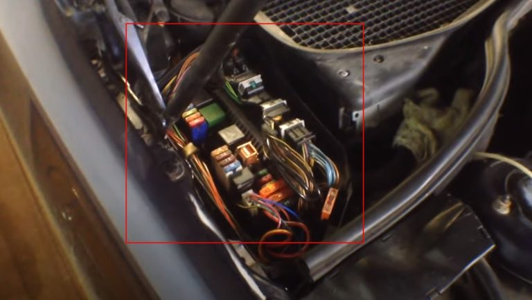
Block on the right side
The second fuse and relay block is located on the right side of the engine compartment.
Marking
| № | Current | Description |
|---|---|---|
| 28 | 15A | Audible signal relay (K40/7kP) |
| 29 | 20A | Relay for electronic engine and chassis control systems (K40/7kK) |
| 30 | 20A | Relay for electronic engine and chassis control systems (K40/7kK) |
| 31 | 40A | Air pump relay (K40/7kN) |
| 32 | 40A | Air compressor relay (K40/7kO) |
| 33 | 40A | Heating system air circulation unit (A32) |
| 34 | 5A | Traction control system control unit (N47) |
| 35 | 15A | from 09.2002 – If there is a steering wheel heater (code 443): Steering wheel heater (R22/4) |
| 36 | 7.5A | If Distronic system is available (code 219a): DTR system control unit (N63/1) |
| 37 | 15A | Cable connector terminal 87 (Z7/5):• control unit of the electronic module of the AT control lever (N15/5)• EGS system control unit (N15/3) |
| 38 | 5A | Interior trunk lid actuator button (KIT) |
| 39 | 40A | Front right door control unit (N69/2) |
| 40 | 10A | If there are xenon headlights (code 612b):headlight range adjustment control unit (N71) |
| 41 | 20A | If there is an autonomous heating system (code 228): via the cable connector of terminal 30 (soldered sleeve in the wiring harness) (Z7/26):• autonomous heater (STH) or additional heater (ZUH) (A6)• STH remote control receiver (A6/1) |
| 42 | 20A | Auxiliary fan relay (K25)• via cable connector terminal 87 (Z7/24) (until 09.2002): |
| 43 | 25A | For diesel engines only:• via cable connector terminal 87 (Z7/47) (until 09.2002):– CDI control unit (N3/9)– starter relay (K40/kL) in the front right relay and fuse box (K40/7) |
| 44 | 7.5A | For diesel engines only:• CDI control unit (N3/9)• intake manifold heating, in the front right relay and fuse box (K40/7) |
| 44 | 10A | Via cable connector terminal 87D2 (Z7/48) (until 09.2002):• CDI control unit (N3/9)• starter relay (K40/kL) in the front right relay and fuse box (K40/7)• electric fan-supercharger for engine and air conditioner with built-in regulator (M4/7)• low-temperature circuit circulation pump (M44) |
| 45 | – | |
| 46 | 5A | If Active Body Control (ABC) is available:• ABC system control unit (N51/2) If air suspension is available:• Airmatic system control unit with ADS (N51) |
| 47 | 10A | Multifunctional sensor KLA (B31/1)Fan motor in electrical equipment protective box (M2/2)Multifunction sensor KLA (B31/1) (until 09.2002)Control of the relay of the additional fan unit of the engine cooling system or the AT oil (K25) via the plug connector (X22/3) (until 09.2002)Through the fan cable electrical circuit (Z5/1) (until 09.2002)• multifunctional sensor KLA (B31/1) (until 09.2002)• control of the relay of the additional fan unit of the engine cooling system or oil in the AT (K25) via the plug connector (X22/3) (until 09.2002)• fan motor in the electrical equipment protective box (M2/2) (until 09.2002) |
| 48 | 7.5A | Blower fan control unit (N65/2) / (from 09.2002 – absent) |
| 48 | 7.5A | Engine and air conditioning blower fan with built-in regulator (M4/7) / (from 09.2002 – absent) |
| 49 | 15A | Via cable connector of protected terminal 15 (Z3/29):• ignition coils (T1/1) – (T1/8)• radio interference suppression capacitor (C4), for Japan and the USA |
Additional unit
Another additional unit is installed under the hood on the right side.
Scheme
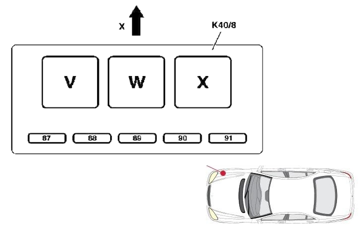
Appointment
| № | Current | Description |
|---|---|---|
| In | Motronic system relay | |
| IN | Charge air relay | |
| X | Fuel module relay in the tank (fuel pump relay) | |
| 87 | 20A | Motronic (K40/8kV), M275/M113 E55 AMG |
| 88 | 20A | Motronic (K40/8kV), M275/M113 E55 AMG |
| 89 | Reserve | |
| 90 | 10A | Charge air relay (K40/8kW), M275/M113 E55 AMG |
| 91 | Reserve |
Blocks in the cabin
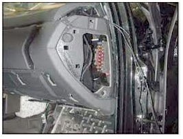
Unit in the instrument panel
There is a fuse box on the right side of the instrument panel, behind a protective cover.
Transcript
| № | Current | Description |
|---|---|---|
| 1 | 7.5A | Steering column control unit, Engine control unit, EIS control unit, Alarm clock |
| 2 | 5A | Instrument panel |
| 3 | 10A | Top control panel module |
| 4 | 10A | Diagnostic Link Connector (DLC) |
| 5 | 10A | Climate control, Air conditioning control unit |
| 6 | 10A | Center console |
| 7 | 5A | Diagnostic Link Connector (DLC) |
| 8 | 5A | Instrument panel |
| 9 | 15A | Cigarette lighter fuse (front), Ashtray lighting |
Fuse number 9 at 15A is responsible for the operation of the cigarette lighter.
Block under the rear seat
There is another block with fuses and relays under the rear passenger seat.
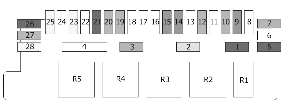
Description
| № | Current | Description |
|---|---|---|
| 1 | 10A | Rear window blind relay |
| 2 | 5A | Slip sensor |
| 3 | 30A | Fuel pump relayAdditional relay, fuel pump |
| 4 | 50A | Rear window heating relay |
| 5 | 10A | Trailer control unit |
| 6 | 25A | Trailer connector |
| 7 | 30A | Trailer control unit |
| 8 | 25A | Closing the luggage compartmentLuggage compartment opening relay |
| 9 | 7.5A | Keyless go control unit |
| 10 | 30A | Control unit (for taxi) |
| 11 | Reserve | |
| 12 | 15A | Voice control unitSpeakerphone |
| 13 | 20A | Pneumatic System Equipment (PSE) |
| 14 | 7.5A | Telephone |
| 15 | 7.5A | Multifunctional control unitAntenna amplifier |
| 16 | Reserve | |
| 17 | 25A | Sound amplifier |
| 18 | 25A | Electric rear seats |
| 19 | 15A | Rear air conditioningCoolant circulation pump |
| 20 | 15A | Rear air conditioning |
| 21 | 10A | Tire pressure monitoring system control unit |
| 22 | 25A | Front left seat belt pretensioner |
| 23 | 40A | Door control unit, rear left |
| 24 | 25A | Seat belt pretensioner, front right |
| 25 | 40A | Door control unit, rear right |
| 26 | 10A | Parking system |
| 27 | 15A | Refrigerator (in the back of the rear seat) |
| 28 | 40A | Overhead console (in the ceiling) |
| R1 | Rear window blind relay | |
| R2 | Slip Sensor Relay | |
| R3 | Terminal 15 relay | |
| R4 | Fuel pump relayAdditional relay, fuel pump | |
| R5 | Rear window heating relay |