Toyota Avensis 2nd generation has the code T25 / T250 and was produced in 2003, 2004, 2005, 2006, 2007, 2008 and 2009. In this article you will find information on the locations of all electronic control units, a detailed description of fuses and relays Toyota Avensis 2 with block diagrams and photo examples of their implementation. Separately, we will highlight the cigarette lighter fuse.

Blocks in the cabin
Location
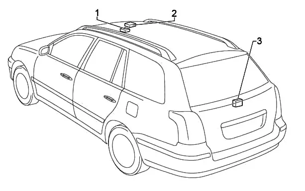
General layout of electronic control units in the cabin
Left hand drive
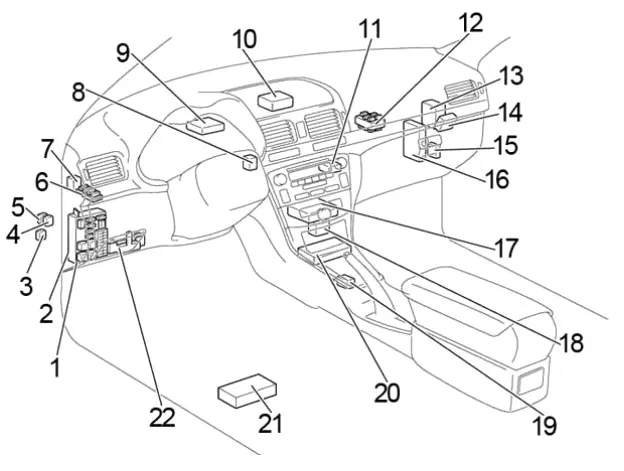
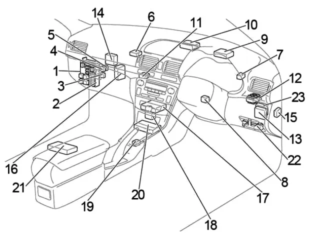
- Fuse box
- Integrated relay
- Fuel Pump Relay (Circuit Opening)
- Rear Fog Light Relay
- Rear window heating relay
- Relay block
- Direction indicator relay
- Key transponder amplifier
- EPS ECU
- Key transponder control unit
- Antenna amplifier
- Distribution block
- Windscreen wiper relay
- Central lock receiver
- Headlight corrector control unit
- Engine and transmission control unit (A/T)
Engine control unit (M/T) - Air conditioning control unit
- Optional connector (navigation)
- Gearbox selector control unit
- Airbag control unit
- Navigation control unit
- Additional fuse box
- RHD: Anti-theft alarm control unit
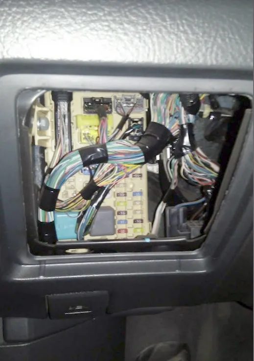
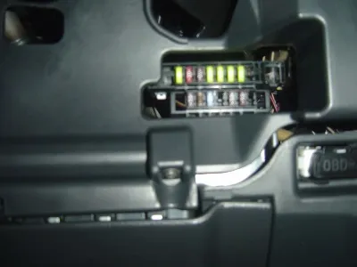
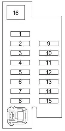
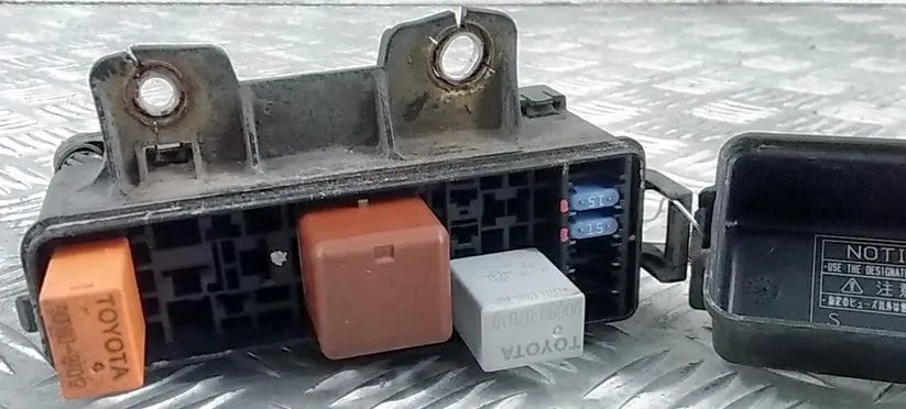
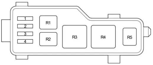
Fuse box
It is located at the bottom of the instrument panel behind a protective cover.
Photo – example
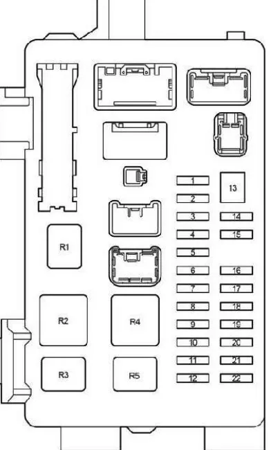
| 1 | 10A IGN – SRS airbags, instrument cluster, starting system, multiport fuel injection system/sequential multiport fuel injection system |
| 2 | 20A S/ROOF – Hatch |
| 3 | 7.5A RR FOG – Rear Fog Light |
| 4 | 15A FR FOG – Front fog light, fog light indicator |
| 5 | 25A AM1 – Starting system, fuses: “CIG”, “RAD NO.1” |
| 6 | 7.5A PANEL – Instrument cluster lighting, instrument cluster lighting, automatic transmission control unit, glove box lighting, armrest compartment lighting, headlamp washers, front fog light, parking assistance system, multi-information display |
| 7 | 20A RR WIP – Rear Wiper and Washer |
| 8 | 7.5A GAUGE2 – Reversing lights, headlight range adjuster, turn signals, hazard warning lights |
| 9 | 15A CIG – Cigarette Lighter |
| 10 | 10A HTR – Heated Seats, Air Conditioning |
| 11 | – |
| 12 | 7.5A RAD NO.1 – Audio system, multi-information display, electric mirrors, instrument cluster, socket |
| 13 | 30A PWR SEAT – Power Seats |
| 14 | 10A TAIL – Side light, number plate light, luggage compartment light, automatic light system, front fog light, rear fog light, instrument cluster |
| 15 | 7.5A OBD2 – Diagnostic connector |
| 16 | 15A P/POINT – Socket |
| 17 | 25A DOOR – Central locking |
| 18 | 25A WIP – Front Wiper and Washer, Headlamp Cleaners |
| 19 | 7.5A ECU-IG – Cooling Fan, Charging System, Power Steering, ABS, VSC |
| 20 | 20A S-HTR – Heated Seats |
| 21 | 10A GAUGE1 – Light switch, multi-information display, integrated relay, instrument cluster, gear selector lock, automatic transmission control unit, interior rearview mirror, windscreen wiper, parking brake |
| 22 | 15A STOP – Brake light bulbs, gear selector lock, additional brake light, multiport fuel injection system/sequential multiport fuel injection system |
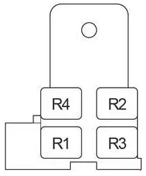
| Relay | |
| R1 | Reserve |
| R2 | HTR – Heater |
| R3 | SEAT HTR – Heated Seats |
| R4 | IG1 – Ignition |
| R5 | TAIL – Side light |
Fuse number 9, 15A, is responsible for the operation of the cigarette lighter.
Additional fuse box
Located above the pedals, parallel to the floor.
| 1 | 25A ACC Start button, immobilizer, steering wheel lock (LHD) |
| 2 | 20A P-RR P/W – Window lifter |
| 3 | 20A P-FR P/W – Window lifter |
| 4 | 20A D-RR P/W – Window lifter |
| 5 | 20A D-FR P/W – Window lifter |
| 6 | 7.5A ECU-B 1 – Gearbox |
| 7 | 10A FUEL OPN – Fuel tank filler flap |
| 8 | 20A FR DIC – Windscreen wiper area heater, fuse: “MIR HTR” |
| 9 | 10A A/C Air Conditioner (Mechanical Air Conditioner), Auxiliary Heater |
| 10 | 7.5A DEF I/UP – Air conditioning |
| 11 | 7.5A ST – Multi-information display, distributed fuel injection system/sequential distributed fuel injection system, starting system |
| 12 | 10A MIR HTR – Heated Mirrors |
| 13 | 15A RAD NO.2 – Audio system, multi-information display |
| 14 | 7.5A DOME – Interior lighting, personal lighting, door lighting, luggage compartment lighting, personal mirror lighting, footwell lighting |
| 15 | 7.5A ECU-B 2 – Air conditioning, wireless control system |
| 16 | 30A PWR SEAT – Power Seats |
Relay block
Scheme
Left hand drive
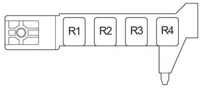
- R1 – Windscreen wiper area heater (FR DEICER)
- R2 – Socket (P/POINT)
- R3 – Front fog light (FR FOG)
- R4 – Starter (ST)
Additional elements
Scheme
- Phone Microphone Amplifier
- Hatch control unit
- Rear wiper relay
Blocks under the hood
Location
General layout of electronic control units under the hood
Option A
(1AZ-FSE, 1AZ-FE, 1ZZ-FE, 3ZZ-FE)
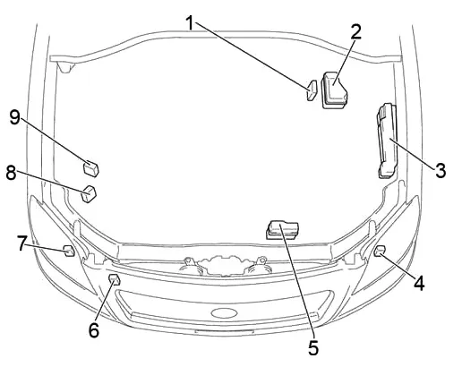
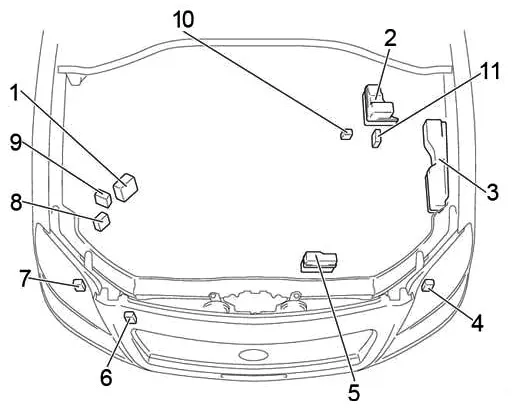
- Injector control unit
- Additional fuse box
- Fuse and relay box
- Left headlight control unit
- Relay block
- Headlight Washer Relay
- Right headlight control unit
- Vehicle Stability Control (VSC)
- Brake control unit (without VSC)
- Glow Plug Relay
- Auxiliary heater
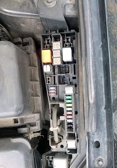
Fuse and relay box
Located on the left side of the engine compartment.
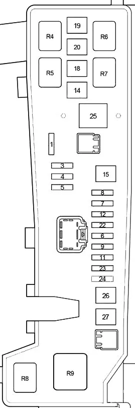
| 1 | – |
| 2 | 25A VSC – 1CD–FTV: ABS, VSC |
| 25A ABS – 1CD–FTV: ABS | |
| 3 | – |
| 4 | – |
| 5 | – |
| 6 | 7.5A ALT-S – Charging System |
| 7 | 30A DCC – Fuses: “ECU-B NO.2”, “DOME”, “RAD NO.2” |
| 8 | 30A AM2 – Starting system, fuses: “ST”, “IGN” |
| 9 | 10A HAZARD – Direction indicators, hazard warning lights |
| 10 | 25A F-HTR – 1CD–FTV: Fuel Preheater |
| 11 | 15A HORN – Horn |
| 12 | 20A EFI – Multiport fuel injection system/sequential multiport fuel injection system, fuses: “EFI NO.1”, “EFI NO.2” |
| 13 | 25A PWR HTR – 1CD–FTV: Auxiliary Heater |
| 14 | 30A RR DEF – Rear Window Defogger |
| 15 | 40A MAIN – Headlamp washers, headlamps, fuses: “H-LP HI LH”, “H-LP HI RH”, “H-LP LH”, “H-LP RH” |
| 16 | 50A AM1 NO.1 – 1CD–FTV: fuses: “ACC”, “CIG”, “RAD NO.1”, “ECU-B NO.1”, “FL P/W”, “FR P/W”, “RL P/W”, “RR P/W” |
| 17 | 30A H/CLN – Headlight cleaners |
| 18 | 40A HTR – Air Conditioner. Heater |
| 19 | 30A CDS – Cooling System Fan |
| 20 | 40A RDI – 1CD–FTV, 1ZZ-FE, 3ZZ-FE: Cooling Fan |
| 30A RDI – 1AZ-FE, 1AZ-FSE: Cooling Fan | |
| 21 | 50A VSC – 1CD–FTV: ABS, VSC |
| 40A ABS – 1CD–FTV: ABS | |
| 22 | 15A IG2 – 1AZ-FSE, 1AZ-FE, 1ZZ-FE, 3ZZ-FE: Starting system, multipoint fuel injection system/sequential multipoint fuel injection system |
| 23 | 10A THROTTLE – 1AZ-FSE, 1AZ-FE, 1ZZ-FE, 3ZZ-FE: Electronic throttle control system |
| 10A ETCS – 1AZ-FSE, 1AZ-FE, 1ZZ-FE, 3ZZ-FE: Electronic Throttle Control System | |
| 24 | 20A A/F – 1AZ-FSE, 1AZ-FE: Air-fuel ratio sensor |
| 25 | 1AZ-FSE, 1AZ-FE, 1ZZ-FE, 3ZZ-FE: – |
| 26 | 1AZ-FSE, 1AZ-FE, 1ZZ-FE, 3ZZ-FE: – |
| 27 | 50A EMPS – 1ZZ-FE, 3ZZ-FE: Power Steering |
| Relay | |
| R1 | EFI MAIN – 1CD–FTV: Cooling Fan |
| R2 | EDU – 1CD–FTV: Cooling system fan |
| R3 | FAN NO.3 – 1CD–FTV: Cooling system fan |
| R4 | FAN NO.1 – Cooling system fan |
| R5 | FAN NO.2 – 1AZ-FSE, 1AZ-FE, 1ZZ-FE, 3ZZ-FE: Cooling system fan |
| R6 | 1AZ-FSE, 1AZ-FE, 1ZZ-FE, 3ZZ-FE: – |
| R7 | FAN NO.3 – 1AZ-FSE, 1AZ-FE, 1ZZ-FE, 3ZZ-FE: Cooling system fan |
| R8 | 1AZ-FSE, 1AZ-FE, 1ZZ-FE, 3ZZ-FE: – |
| R9 | EMPS – 1ZZ-FE, 3ZZ-FE: Power Steering |
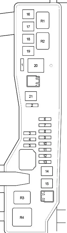
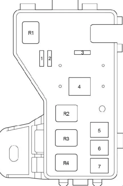
Additional fuse box
Scheme
Option A
| 1 | – |
| 2 | 50A HTR2 – Auxiliary Heater |
| 3 | 50A HTR1 – Auxiliary Heater |
| 4 | 80A GLOW – Glow Plugs |
| 5 | 140A ALT – Relays: “IG1”, “TAIL”, “SEAT HTR”, fuses: “H-LP CLN”, “AM1 NO.1”, “RDI”, “CDS”, “VSC” (50A), “VSC” (25A), “ABS” (40A), “ABS” (25A), “H/CLN”, “RR DEF”, “GLOW”, “HTR” NO1”, “HTR NO2”, “RFGHTR”, “AM1 NO.2”, “RR FOG”, “S/ROOF”, “STOP”, “P/POINT”, “FR FOG”, “OBD2”, “DOOR” |
| Relay | |
| R1 | |
| R2 | HTR2 – Auxiliary heater |
| R3 | HTR1 – Auxiliary heater |
Option B
| 1 | 10A EFI NO.1 – Multiport fuel injection system/sequential multiport fuel injection system |
| 2 | 7.5A EFI NO.2 – Emission Control System |
| 3 | 25A VSC – ABS, VSC |
| 25A ABS – ABS | |
| 4 | 100A ALT – 1ZZ-FE, 3ZZ-FE: Fuses: “AM1 NO.1”, “H-LP CLN”, “ABS” (25A), “VSC” (25A), “ABS” (40A), “VSC” (50 A), “CDS”, “RDI”, “HTR”, “RR DEF”, “RR FOG”, “FR FOG”, “AM1”, “DOOR”, “STOP”, “OBD2”, “S/ROOF”, “PWR SEAT”, “P/POINT”, “TAIL”, “PANEL”, “RR WIP”, “ECU-IG”, “WIP”, “GAUGE2”, “GAUGE1”, “HTR” ,”S-HTR” |
| 120A ALT – 1AZ-FSE, 1AZ-FE: Fuses: “AM1 NO.1”, “H-LP CLN”, “ABS” (25A), “VSC” (25A), “ABS” (40A), “VSC” (50 A), “CDS”, “RDI”, “HTR”, “RR DEF”, “RR FOG”, “FR FOG”, “AM1”, “DOOR”, “STOP”, “OBD2”, “S/ROOF”, “PWR SEAT”, “P/POINT”, “TAIL”, “PANEL”, “RR WIP”, “ECU-IG”, “WIP”, “GAUGE2”, “GAUGE1”, “HTR” ,”S-HTR” | |
| 5 | 50A VSC – ABS, VSC |
| 40A ABS – ABS | |
| 6 | 50A AM1 NO.1 – Fuses: “PWR SEAT”, “FR DIC”, “FUEL OPN”, “ECU-B 1″, P-RR P/W”, “P-FR P/W”, “D-RR P/W”, “D-FR P/W” |
| 7 | 30A H-LP CLN – Headlight cleaners |
| Relay | |
| R1 | INJ – Injector |
| R2 | EFI – Engine Control Unit |
| R3 | IG2 – Ignition |
| R4 | A/F – Air Fuel Ratio Sensor |
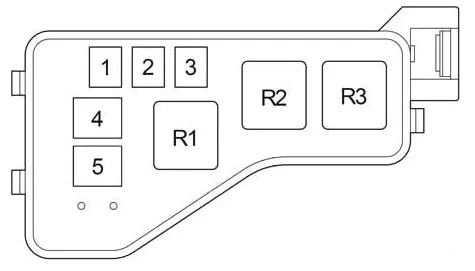
Relay block
Photo – example
| 1 | 10A H-LP HI LH – Left headlight (high beam) |
| 2 | 10A H-LP HI RH – Right headlight (high beam), instrument cluster |
| 3 | 15A H-LP LH – Left headlight (low beam) |
| 4 | 15A H-LP RH – Right headlight (low beam) |
| Relay | |
| R1 | HORN – Sound signal |
| R2 | F-HTR – Fuel Heating |
| R3 | H-LP – Headlights |
| R4 | DIM – Dimmer |
| R5 | FAN NO.2 – Cooling system fan |