Ford Transit 7th generation was produced in 2006, 2007, 2008, 2009, 2010, 2011, 2012 and 2013. This model has received a serious update compared to previous models. In our article you will find a description of the fuse blocks and relays Ford Transit 7 their diagrams and photos. Let’s highlight the fuse responsible for the cigarette lighter. At the end, we will offer to download the complete manual Ford Transit 7th generation.

Block arrangement
Locations of fuse and relay blocks
Scheme
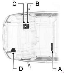
- A — Additional fuse block
- B – Fuse and relay block
- C – Main fuse block
- D – Underhood fuse box
Blocks in the cabin
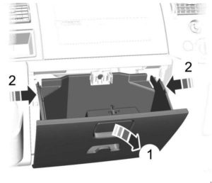
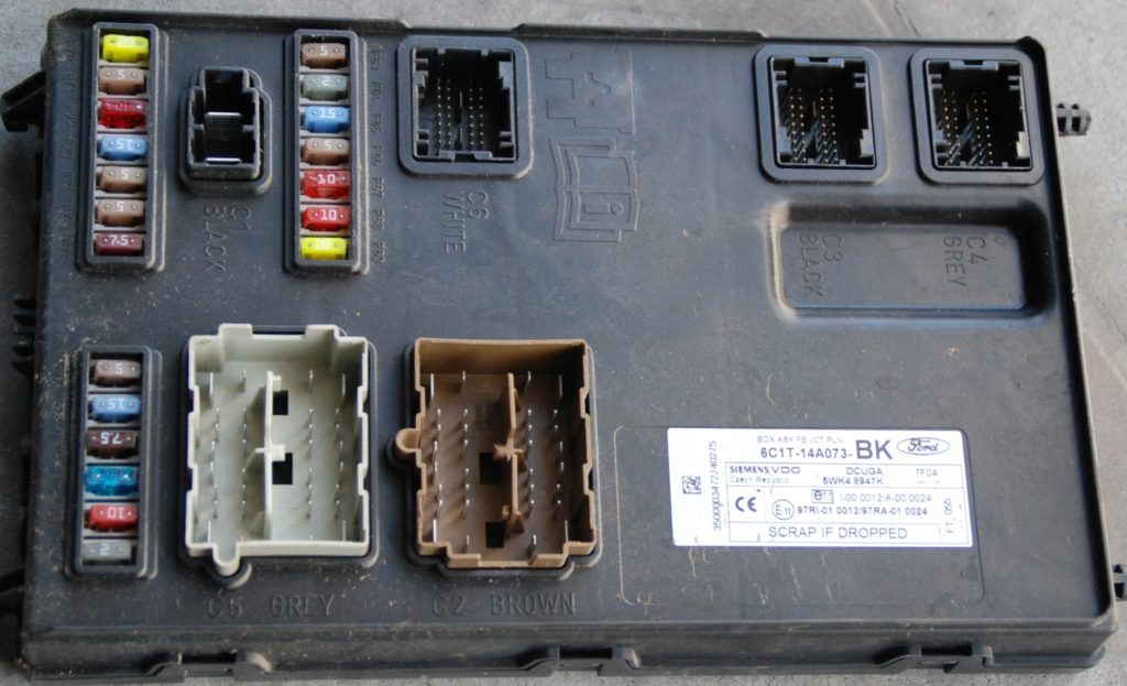
Fuse and relay block
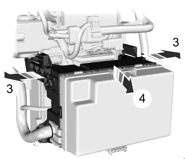
It is located behind the glove compartment, so to get to it you need to remove the glove compartment itself and remove the protective cover of the unit. On the back of which the current diagram will be applied.

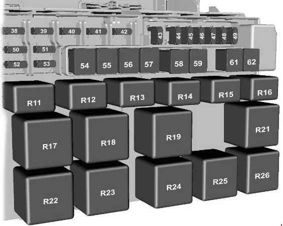
Description
| 38 | 20A Rear window wiper |
| 39 | 10A Front and rear air conditioning controls |
| 40 | 5A Not used |
| 41 | 5A Tachograph |
| 42 | 5A Light beam level adjustment system, main switch (KL15) |
| 43 | 20A Electric front seat heating |
| 44 | 20A Audible signal |
| 45 | 20A Front auxiliary power socket |
| 46 | 10A Heated side rear view mirrors, if CAT 1 is installed |
| 47 | 20A Cigarette lighter |
| 48 | 5A Power supply for relay coils, electric mirrors |
| 49 | 20A Rear auxiliary power socket |
| 50 | 10A High beam headlights, left side |
| 51 | 10A High beam headlights, right side |
| 52 | 10A Low beam headlights (left side) |
| 53 | 10A Headlight low beam, right side |
| 54 | 30A Fuse for the circuits for switching on the low and high beam headlights, daytime running lights, tachograph and auxiliary fuel heater fan |
| 55 | 40A Heater fan motor |
| 56 | 20A Electric window regulator |
| 57 | 30A Rear passenger compartment heater fan motor |
| 58 | 30A Front wiper motor |
| 59 | 30A Rear window and rear-view mirror heaters |
| 60 | Reserve |
| 61 | 60A Ignition Relay (KL5 #1) |
| 62 | 60A Ignition Relay (KL5 #2) |
| Relay | |
| R11 | Headlight low beam activation circuit |
| R12 | Heated exterior mirrors (if CAT 1 alarm is installed). Power socket (if CAT 1 alarm is not installed) |
| R13 | Headlights – high beam |
| R14 | Sound signal |
| R15 | Lighting when driving during daylight hours |
| R16 | Programmable fuel heater |
| R17 | Heated rear window or rear-view mirrors (or heated right rear window if CAT 1 alarm is installed) |
| R18 | Heated rear window (right side) if CAT 1 alarm is installed |
| R19 | Forced Submission (KL15 #2) |
| R20 | Electrical junction box on passenger side KL15 (only vehicles with engine start/stop system) |
| R21 | Forced Submission (KL15 #1) |
| R22 | Heated windshield, right side |
| R23 | Wiper (high and low speed) |
| R24 | Rear window wiper |
| R25 | Windshield wiper (on and off) |
| R26 | Heated windshield, left side |
Fuse number 47 at 20A is responsible for the cigarette lighter.
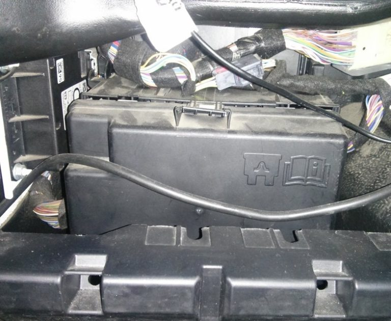
Main fuse block
It is located behind the fuse and relay box. To find it, you need to press the 2 latches on the sides.
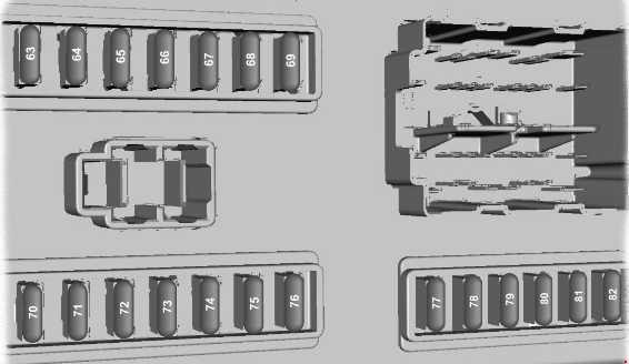
Appointment
| 63 | 5A Reverse parking assist system, rain sensor |
| 64 | 2A Accelerator pedal position sensor |
| 65 | 15A Stop signal switch |
| 66 | 5A Instrument panel, PATS security system power supply, tachograph, control panel backlight |
| 67 | 15A Washer pump |
| 68 | 10A Restraint systems control unit |
| 69 | 20A Outdoor lighting switch (KL15) |
| 70 | 20A Echo sounder with emergency power supply |
| 71 | 5A Outdoor lighting switch (KL30) |
| 72 | 10A Battery power consumption regulator power supply. OBDII (KL30) |
| 73 | 15A Power supply for audio and navigation system units and mobile phone |
| 74 | 5A Instrument panel, auxiliary heater timer, keyless entry system power supply, interior motion sensor (K1_30) |
| 75 | 7.5A Side lights on the right side |
| 76 | 7.5A Side lights on the left side |
| 77 | 5A Power supply for the ignition switch, power supply for the battery disconnection sensor windings |
| 78 | 15A Central locking system |
| 79 | 7.5A License plate light, side marker lights |
| 80 | 15A Front fog lights |
| 81 | 10A Rear fog lights |
| 82 | 3A Regular power supply for the audio unit and instrument panel |
There may be several separate fuses:
- 83 – 10A – Towed trailer electrical control module, located in the footwell on the left side
- 84 – 7.5A – DPF – glow plug control is located in the electrical distribution box located under the engine compartment
Additional fuse block
It is located behind the back of the driver’s seat, under a protective cover. The seat must be moved to access it.

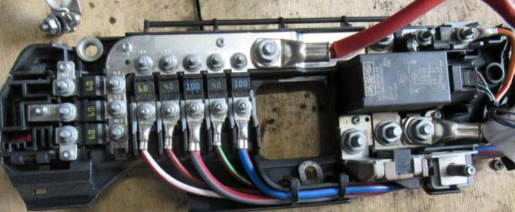
Marking
| 1 | 350A Starter and Alternator |
| 2 | 60A Power to the passenger side electrical junction box that provides engine start. Passenger side electrical junction box for engine start/stop system |
| 3 | 100A Power supply to the junction box in the engine compartment (not important for starting) |
| 4 | 40A Electric windshield heater, right side |
| 5 | 100A Power supply to standard relay block (not essential for starting) |
| 6 | 40A Electric windshield heater, left side |
| 7 | 60A Power supply to the distribution box in the cabin (not important for starting) |
| 8 | 60A User connector |
| 9 | 60A User connector |
| 10 | 60A User connector |
- R1 – Second battery switch
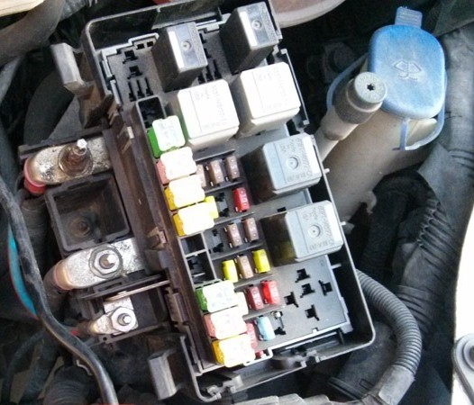
Block in the engine compartment
Located on the left under the protective cover.
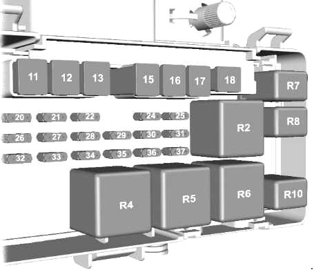
Description
| 11 | 60A Engine cooling system fan motor |
| 12 | 30A Trailer Hitch and Trailer Hitch Unit Power Circuits (KL30) |
| 13 | 40A ABS and ESP pump |
| 14 | Reserve |
| 15 | 60A Glow plugs |
| 16 | 60A Ignition Relay (KL15 #3) |
| 17 | 30A Starter activation |
| 18 | 40A Between the ignition system power circuit (KL15) and the passenger side electrical junction box (vehicles without engine start/stop system) |
| 18 | Reserve (vehicles with engine start/stop system) |
| 19 | Reserve |
| 20 | 10A Power supply for ABS. ESP. steering shaft position sensor and risk sensor (YAW) (KL30) |
| 21 | 25A ABS and ESP valves and control unit |
| 22 | Reserve |
| 23 | Reserve |
| 24 | 5A Fuel pump (vehicles without fuel-powered auxiliary heater) |
| 24 | 20A Fuel pump (vehicles with fuel-powered auxiliary heater) |
| 25 | Reserve |
| 26 | 15A PCM Power Relay |
| 27 | 5A Fuel pump (vehicles with fuel-powered auxiliary heater) |
| 28 | 5A Combined temperature and mass air flow sensor (T-MAF) |
| 29 | 5A Evaporator glow plug monitoring |
| 30 | 7.5A Sound purge valve |
| 31 | 15A YAP/UEGO Pump |
| 32 | 20A Evaporator glow plug |
| 33 | 10A Reversing lights |
| 34 | 20A Trailer Power Supply KL15 |
| 35 | Reserve |
| 36 | 10A Air conditioning compressor clutch |
| 37 | Reserve |
| Relay | |
| R2 | Glow plugs |
| R3 | Trailer towing (KL15) |
| R4 | Turning on the starter |
| R5 | Forced Submission (KL15 #4) |
| R6 | Forced Submission (KL15 #3) |
| R7 | Fuel pump |
| R8 | Evaporator glow plug |
| R9 | Not used |
| R10 | Air conditioner compressor clutch solenoid |