The Mazda CX-9 all-wheel drive crossover has been produced in two generations since 2007. The Mazda CX-9 TB , the first generation, was delivered to the markets in 2008, 2009, 2010, 2011, 2012, 2013, 2014, 2015 and 2016. The second generation, the Mazda CX-9 TC , was assembled in 2017, 2018, 2019, 2020, 2021 and to the present. In this article you will find information describing the fuses and relays of the Mazda CX9 with block diagrams and their locations for two generations. We note the cigarette lighter fuse.

The design of the blocks and the number of elements in them may differ from the one presented and depend on the year of manufacture and equipment level. Check your diagrams, and in case of difficulties, contact your nearest dealer.
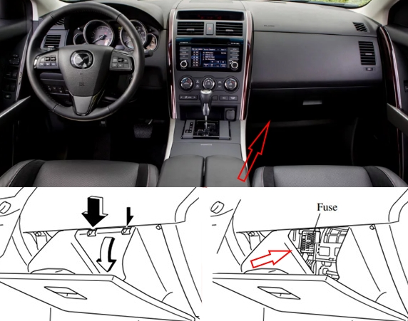
Cabin block
First generation
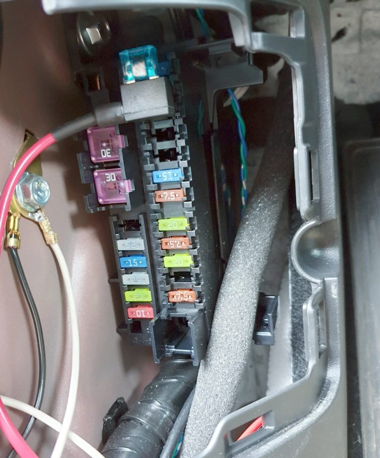
It is located under the panel behind the glove compartment; to access it, you need to open the protective cover behind the arrow.
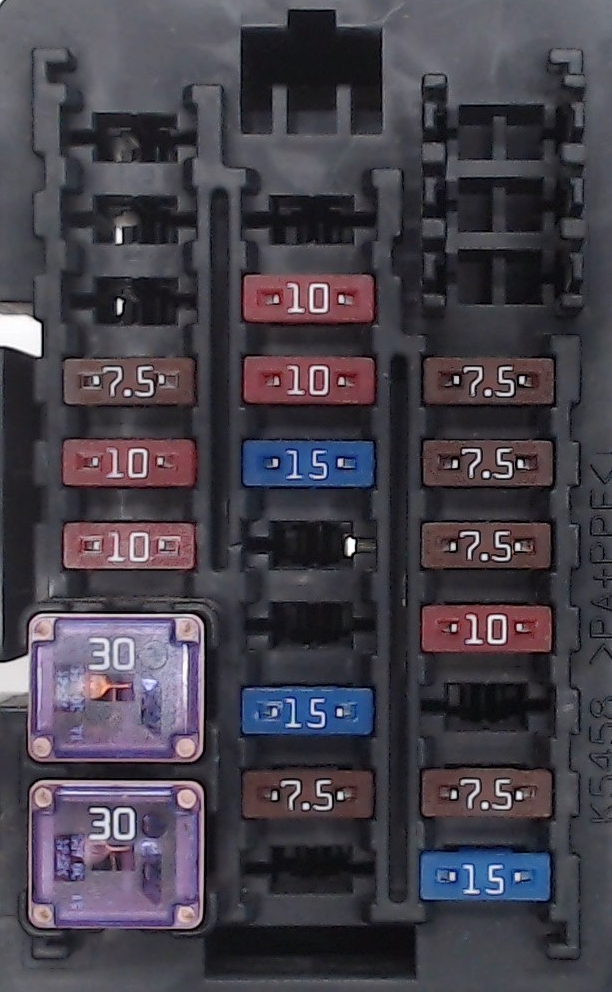
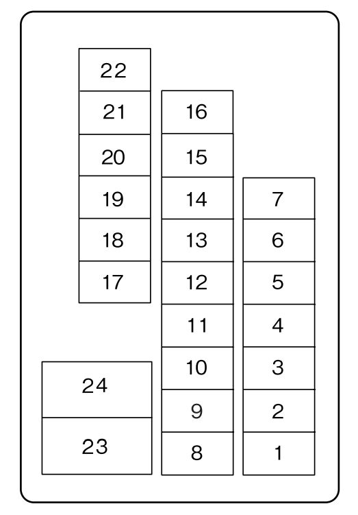
Description
| 1 | 15A OUTLET FR – Accessory socket (front), cigarette lighter |
| 2 | 7.5A MIRROR – Mirrors and their controls |
| 3 | Reserve |
| 4 | 10A METER – Instrument panel |
| 5 | 7.5A SAS – ABS, airbag |
| 6 | 7.5A ENG.IGA – Engine Management System |
| 7 | 7.5A STA – Ignition system |
| 8 | Reserve |
| 9 | 7.5A A/C – Air conditioner |
| 10 | 15A R.WIPER – Rear window wiper and washer |
| 11 | TRAILER – Priced device |
| 12 | 20A P.LIFT GATE – Gate with mechanical lift |
| 13 | 15A SUNROOF – Sunroof |
| 14 | 10A AUDIO – Audio system |
| 15 | 10A M.DEF – Heated mirrors |
| 16 | 25A P/W – Power windows (passenger side) |
| 17 | 10A TAIL – Dimensions, Taillight |
| 18 | 10A ILLUMI – Instrument panel lighting |
| 19 | 7.5A INJ – Engine Management System |
| 20 | Reserve |
| 21 | OUTLET CTR – Accessory connector |
| 22 | OUTLET RR – Rear accessory outlet |
| 23 | 30A WIPER – Windshield wiper and washer |
| 24 | 30A P.WIND – Power windows (driver’s side) |
The fuses marked OUTLET are responsible for the operation of cigarette lighters.
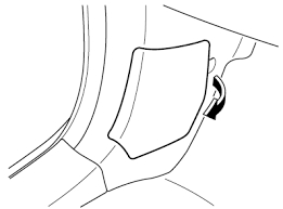
Second generation
It is installed under a protective cover on the left pillar near the driver’s foot.

Transcript
| 1 | 30A P.SEAT D – Electric seat adjustment drive (for some versions) |
| 2 | 30A P.WINDOW 3 – Electric windows |
| 3 | 15A R.OUTLET3 – Additional electrical outlets |
| 4 | 25A P.WINDOW 2 – Electric windows |
| 5 | 20A PLG – Power tailgate |
| 6 | 25A D.LOCK – Central electric lock |
| 7 | 20A SEAT WARM – Electric seat heating (for some versions) |
| 8 | 15A SRS2/ESCL – Passive safety, airbags |
| 9 | 10A SUNROOF – Sunroof (for some versions) |
| 10 | 10/15A INTERIOR2 – Audio system |
| 11 | 7.5A ENG+BB – Engine Management System |
| 12 | 7.5A MIRROR – Electric drive for adjusting rear-view mirrors |
| 13 | 7.5A AT IND – Gear shift indicator |
| 14 | 15A F.OUTLET – Cigarette lighter, electrical outlets |
| 15 | 15A R.OUTLET1 – Rear electrical outlets (for some versions) |
| 16 | Reserve |
| 17 | 7.5A M.DEF – Electric heated exterior mirrors |
| 18 | Reserve |
| 19 | 15A AUDIO3 – Audio system |
| 20 | Reserve |
| 21 | 30A P.SEAT P – Electric seat adjustment drive |
The cigarette lighter fuses are marked OUTLET at 15A and are located under numbers 3, 14 and 15. Another fuse and relays responsible for the operation of the power outlets can also be mounted in the unit under the hood.
Blocks under the hood
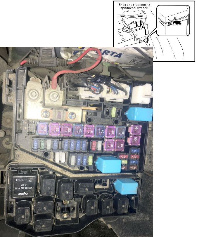
In both generations, the unit is located on the left side of the engine compartment next to the battery.
First generation
example
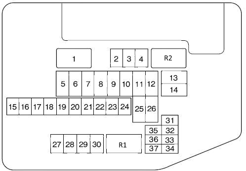
Appointment
| 1 | 150A MAIN – Protection of all electrical circuits |
| 2 | 20A ENGINE – Engine control system |
| 3 | 40A R HEATER – Rear heater |
| 4 | 40A P.SEAT R – Electric drive for adjusting the right seat |
| 5 | 50A HEATER – Heater |
| 6 | 40A IGKEY2 – Protection of various electrical circuits |
| 7 | 30/40A FAN1 – Engine radiator cooling fan |
| 8 | 40A P.SEAT L – Electric drive for adjusting the left seat |
| 9 | 30A DEFOG – Electric rear window heater |
| 10 | 40A BTN – Protection of various electrical circuits |
| 11 | 30A FUEL PUMP – Fuel pump |
| 12 | 30A IGKEY1 – Protection of various electrical circuits |
| 13 | 15A FOG – Fog lights |
| 14 | 30A ABS (SOL) – ABS unit solenoid |
| 15 | 25A D/L – Central electric lock |
| 16 | 15A ROOM – Upper interior lighting lamps |
| 17 | 15A OUTLET CTR – Power outlet for additional equipment |
| 18 | 25A ACC – Electrical socket |
| 19 | 15A AC PWR – Power supply hatch, inverter |
| 20 | 15A S.WARM – Electric seat heater |
| 21 | 10A A.CMAG – Air conditioner |
| 22 | 25A BOSE – Audio system (cars equipped with BOSE audio system) |
| 23 | 30/40A FAN 2 – Engine radiator cooling fan |
| 24 | 50A ABS – Anti-lock Braking System (ABS) |
| 25 | 25A IGCOIL – Ignition system |
| 26 | 15A H/L LOW L – Left low beam headlight |
| 27 | 15A H/L LOW R – Right low beam headlight |
| 28 | 20A H/L HIGH – High beam headlights |
| 29 | 15A HAZARD – Emergency light signal |
| 30 | 10A ENG+B – PCM control unit |
| 31 | 15A HORN – Sound signal |
| 32 | 7.5A STOP – Stop signals |
| 33 | 10A EG I INJ – Engine Management System |
| 34 | 20A ENG BAR – Air flow sensor, exhaust gas recirculation valve |
| 35 | 7.5A ENG BAR2 – PCM control unit |
- R1 FUEL PUMP RELAY – Fuel pump relay
- R2 EGI MAIN RELAY – Main engine control relay
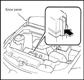
Additional elements can be mounted outside these blocks, for example, there may be another relay block to the right of the engine compartment.
Second generation
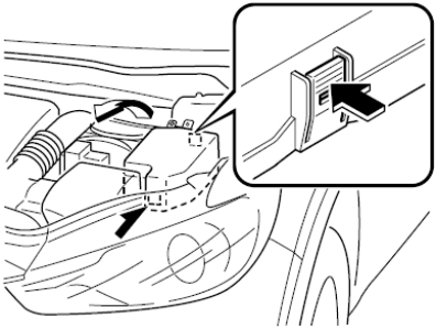
Photo – example of execution
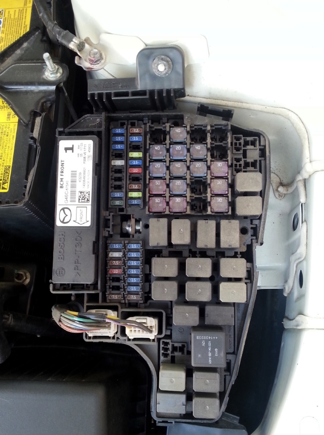
Scheme
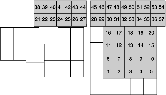
Marking
| 1 | 20A WIPER.DEI – windshield wiper deicer |
| 2 | 30A IG2 – For protection of various circuits |
| 3 | 30A INJECTOR – Engine control system, injection |
| 4 | Reserve |
| 5 | 30A P. WINDOW 1 – Glass lifts |
| 6 | 30A W. SEAT – Power Seat |
| 7 | Rezera |
| 8 | 20A EVVT – Engine Management System |
| 9 | 40A DEFOG – Heated rear window |
| 10 | 20A Heated steering wheel |
| 11 | 40A R.HEATER – Air conditioner |
| 12 | 20A EPB L – Electric Parking Brake (EPB) (LH) |
| 13 | 40A AUDIO – Audio system |
| 14 | 20A EPB R – Electric Parking Brake (EPB) (RH) |
| 15 | 40A ENG.MAIN – Engine control system |
| 16 | 50A ABS/DSC M – ABS, Dynamic Stability Control System |
| 17 | 50A CABIN.+B – For protection of various circuits |
| 18 | 20A WIPER – Windshield wiper and washer |
| 19 | 40A HEATER – Air conditioner |
| 20 | Reserve |
| 21 | 7.5A ENGINE.IG1 – Engine management system |
| 22 | 15A C/U IG1 – For protection of various circuits |
| 23 | 15A H/L LOW L – Low beam headlights – left |
| 24 | 15A H/L LOW R – Low beam headlights – right |
| 25 | 15A ENGINE3 – Engine management system |
| 26 | 15A ENG1NE2 – Engine Management System |
| 27 | 15A ENG1NE1 – Engine Management System |
| 28 | 15A AT – Transmission control system, Ignition switch. |
| 29 | 20A H/CLEAN – Headlight cleaner/washer |
| 30 | 7.5A A/C – Air conditioner |
| 31 | 15А AT PUMP |
| 32 | 10A STOP – Stop signals |
| 33 | 15A R.WIPER – Rear window wiper, Anti-theft system |
| 34 | 20A H/L HI – High beam headlights |
| 35 | 15A H/L LOW R2 – Low beam headlights (right) |
| 36 | 15A FOG – Fog lights (some models) |
| 37 | 7.5A ENG.+B – Engine control system |
| 38 | 7.5A AUDIO2 – Audio system (some models) |
| 39 | 10A INTERIOR – Light, For protection of various circuits |
| 40 | 15A METER2 – Instrument panel |
| 41 | 10A METER1 – Instrument panel |
| 42 | 7.5A SRS1 – Airbag |
| 43 | 10A AUDIO4 – Audio system (some models) |
| 44 | 25A AUDIO1 – Audio system |
| 45 | 30A ABS/DSC S – ABS, Dynamic Stability Control System |
| 46 | Reserve |
| 47 | 15A ST.HEATER – Steering wheel heating |
| 48 | 15A TAIL – Dimensions, Parking lights |
| 49 | 25A FUEL PUMP2 – Fuel system |
| 50 | 25A HAZARD – Hazard warning lights, turn signals, tail lights |
| 51 | 15A DRL – Daytime Running Lights |
| 52 | 15A R.OUTLET2 – Accessory sockets |
| 53 | 15A HORN – Signal |
| 54 | 25A ROOM – Interior and trunk lighting |
To turn off the headlight washer, you need to remove fuse number 29 at 20A marked H/CLEAN .