The first generation Peugeot 308 was produced in 2007, 2008, 2009, 2010, 2011 and 2012. After restyling, the second generation was produced in 2013, 2014, 2015, 2016, 2017, 2018 and to the present. The most common body variants are: hatchback, sedan, station wagon SW , coupe SS. In this publication we will show where the fuse and relay blocks are located in the Peugeot 308 with their diagrams and note the cigarette lighter fuse.

Arrangement
Scheme
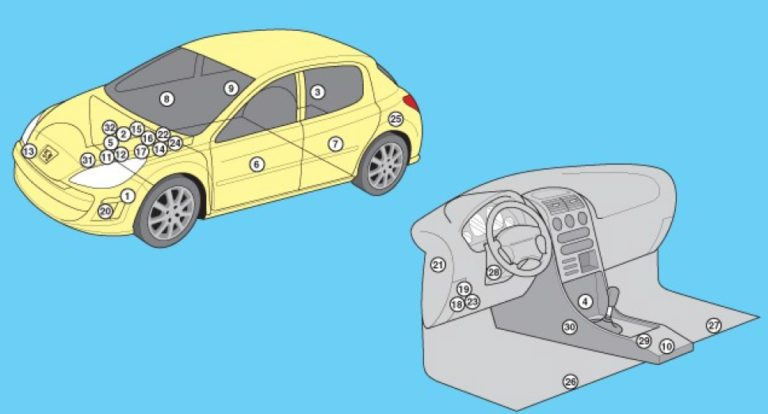
Description of elements
- ABS electronic control unit
- Rechargeable battery
- Glove box drive relay with central locking system
- Roof folding control unit – behind the right rear trim panel
- Diagnostic Connector (DLC)
- Daytime running light relay
- Driver’s door electrical control unit
- Left rear door electrical control unit
- Passenger door electrical control unit
- Right rear door electrical control unit
- ESP control unit (Electric Stability Program)
- Engine control system relay
- Electronic Engine Control Module (ECM)
- Cooling system fan motor control unit
- Fuse/relay block, engine compartment 1
- Fuse/relay block, engine compartment 2
- Fuse/relay block, engine compartment 3
- Fuse/relay block, engine compartment 4
- Fuse/relay block, instrument panel 1
- Fuse/relay block, instrument panel 2
- Sound signal
- Marking tracking system control unit
- Multifunction control unit 1 – in the fuse/relay block under the instrument panel 1
- Multifunction control unit 2 – built into the fuse/relay block in the engine compartment 1
- Multifunction control unit 3- in the fuse/relay block under the instrument panel 1
- Parking system control unit – behind the left rear trim panel
- Driver’s seat heating control unit
- Passenger seat heating control unit
- Steering column electrical control unit
- SRS electronic control unit
- Transmission Control Module (TCM) – Transmission ASM
Blocks under the hood
There are 2 fuse blocks in the engine compartment. One on the battery, the other next to it. See the video for more details.
Main unit with fuses
General scheme
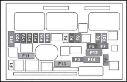
Designation (Option 1)
| F10 – 30A | Components of the electronic control system for a gasoline engine: ignition coils, solenoid valves, oxygen concentration sensors, injectors, heating system elements, fuel pump, electronic thermostat; for a diesel engine: solenoid valves, heating system elements |
| F20 – 10A | Electronic thermostat, fuel control solenoid valves, turbocharger pressure control solenoid valve (diesel engine), coolant level sensor (diesel engine) |
| F19 – 15A | Oil vapor heater (1.4 l 16V and 1.6 l VTi 16V), adsorber solenoid valve (1.4 l 16V and 1.6 l VTi 16V), oxygen concentration sensors (petrol engine), air cooling system solenoid valves (diesel engine) |
| F18 – 15A | Right headlight (low beam) |
| F17 – 15A | Left headlight (low beam) |
| F16 – 10A | Left headlight (high beam) |
| F15 – 10A | Right headlight (high beam) |
| F4 – 20A | headlight washer |
| F2 – 15A | Sound signal |
| F10 – 10A | Diagnostic connector, headlights with directional light distribution, air flow sensor (diesel engine), pump for supplying additive to the particulate filter (diesel engine) |
| F21 – 10A | Vehicle speed sensor circuit, ABS/ESP ECU |
| F7 – 5A | Engine cooling fan relay power supply, Valvetronic relay switch (1.4L 16V and 1.6L VTi 16V), turbocharger cooling (1.6L THP 16V), air flow sensor (1.6L HDI 16V) |
| F12 – 10A | Power steering ECU, automatic transmission, coolant level sensor |
| F8 – 30A | Low/high speed windshield wiper |
| F14 – 25A | Starter switch |
| F3 – 30A | Turbocharger pressure solenoid valve |
| F13 – 10A | Peugeot 308 front and rear window washer fuse |
| F11 – 40A | Power supply of the intelligent switching unit (“+” from the ignition switch) |
| F1 – 40A | Air conditioning fan |
| F5 – 20A | Engine ECU power supply, unit injector solenoid valves and EGR exhaust gas recirculation system (on 2.0 l HDI 16V engine), injectors (on 2.0 l HDI 16V engine) |
| F6 – 15А | Adsorber solenoid valves, electric turbocharger pressure reducing valve (1.6L THP 16V engine), oil vapor heater (1.6L THP 16V), diesel fuel heater (1.6L HDI 16V) |
Designation (Option 2)
- F1 Engine ECU power supply, pump-injector solenoid valves and EGR exhaust gas recirculation system (on 2 liter HDI 16V engine), injectors (on 2 liter HDI 16V engine) – 20 A
- F2 Audible signal – 15 A
- F3 Windshield washer – 10 A
- F4 Headlight washer – 20 A
- F5 Adsorber solenoid valves, turbocharger electric pressure reducing valve, oil vapor heater, diesel fuel heater (on 1.6 l HDI 16V engine) – 15 A
- F6 Vehicle speed sensor circuit, ABS/ESP ECU – 10 A
- F7 Power steering ECU, automatic transmission, coolant level sensor – 10 A
- F8 Starter switch – 25 A
- F9 Diagnostic connector, adaptive headlights, air flow sensor (on diesel), pump for supplying additive to the particulate filter (on diesel), exterior mirror drives – 10 A
- F10 Components of the electronic engine control system (on gasoline: ignition coils, solenoid valves, oxygen sensors, injectors, heating system elements, fuel pump, electronic thermostat; on diesel: solenoid valves, heating system elements) – 30 A
- F11 Air conditioning fan – 40 A
- F12 Windshield wiper low/high speed – 30 A
- F13 Intelligent switching unit power supply (“+” from the ignition switch) – 40 A
- F14 Peugeot 308/308 SW Turbo boost pressure solenoid valve – 30 A (Peugeot 308 CC Not used)
- F15 Right high beam headlight – 10 A
- F16 Left high beam headlight – 10 A
- F17 Left high beam headlight – 15 A
- F18 Right high beam headlight – 15 A
- F19 Oil vapor heater (1.6 l VTI 16V), adsorber unloading solenoid valve (1.6 l VTI 16V), oxygen sensors (on gasoline engines), air cooling system solenoid valves (diesel) -15 A
- F20 Electronic thermostat, fuel control solenoid valves, turbocharger pressure control solenoid valve (diesel), coolant level sensor (diesel) – 10 A
- F21 Engine cooling fan relay power supply, Valvetronic relay control (1.6 l 16V), turbocharger cooling (1.6 l TFIP 16V), air flow sensor (1.6 l FIDI 16V) – 5 A
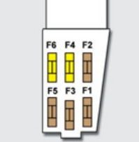
Battery cover unit
Description Option 1.
Scheme
Purpose of fuses
| F1 – 15A | Transmission (sequential or automatic) |
| F2 – 15A | Diagnostic connector, daytime running lights |
| F3 – 5A | Dual-function brake system contactor |
| F4 | Reserve |
| F10 – 80A | Power steering pump |
| F9 – 70А | Heating system ECU (diesel engine) |
| F8 – 100A | Switch unit and protection system |
| F7 | Reserve |
| F6 – 30A | Sequential gearbox electric pump |
| F5 | Valvetronic system electric motor (1.6L THP 16V) |
Maxi fuses
Description Option 2.
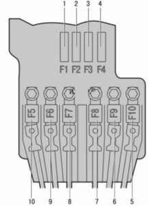
Scheme
Appointment
F1 – Not used.
F2 – 5 A Dual function brake contactor.
F3 – 5 A Battery charge circuit processor.
F4 – 25 A ABS/ESP solenoid valves.
F5 – Not used.
F6 – 15 A Transmission (manual or automatic)
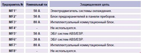
Maxi fuses
| MF1* | Not used |
| MF2* | 30A Trailer Switch Box |
| MF3* | 50A Electrical fuse box in the passenger compartment |
| MF4* | 80A Intelligent Switching Unit |
| MF5* | 80A Intelligent Switching Unit |
| MF6* | Not used |
| MF7* | 30A Seat heating |
| MF8* | 20A Headlight washer |
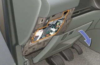
Cabin block
This fuse box is located under the instrument panel (on the left).
Option 1
Scheme
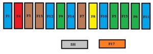
Transcript
| F11 | 15 | Ignition switch low current circuit |
| F6 | 30 | Rear windows |
| F15 | 30 | Locking and superlocking |
| F5 | 30 | Front windows, power, folding rear-view mirror drives, panoramic roof blind |
| F10 | 15 | |Steering wheel switches, alarm siren, alarm system ECU |
| F8 | 20 | Audio system, radio telephone, CD changer, multifunction display, tire pressure monitoring system |
| F7 | 5 | Front and rear ceiling lights, individual lighting ceiling lights, rear spot ceiling lights, mirror lighting on sun visors, glove box lighting, portable lamp |
| F14 | 15 | Multifunction display, amplifier, Hands free device, rain/light sensor, parking assist ECU, trailer switch unit, lane departure warning system |
| F9 | 30 | 12 V front socket, cigarette lighter fuse |
| F12 | 15 | Instrument cluster, front passenger seat belt and airbag warning light panel, air conditioning, driver’s seat memory unit, 2nd row seat area switches, training vehicle module |
| F13 | 5 | Electronic engine management system unit, airbags, sequential automatic transmission selector lever |
| F3 | 5 | Airbag and pyrotechnic pretensioner ECUs |
| F4 | 10 | Clutch pedal contactor and dual-function brake system contactor, interior photosensitive rearview mirror, air conditioner, steering wheel position sensor, automatic transmission, protection system switching unit |
| F1 | 15 | Rear window wiper |
| F17 | 40 | Heated rear window and exterior mirrors |
| SH | – | Shunt PARC |
Fuse number 9 at 30A is responsible for the cigarette lighter.
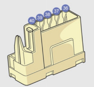
The following elements are placed separately:
G36 – 30 A Heated driver and passenger seats.
G37 – 5 A Driver settings memory unit, lighting control.
G38 – 30 A Driver seat memory unit.
G39 – 30 A Trailer switch unit power supply circuit.
G40 – 30 A Hi-Fi amplifier.
Option 2
General scheme
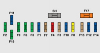
Marking
- F1 15 A Rear window wiper.
- F2 30 A Locking and deadlocking system ground.
- F3 5 A Airbag and pretensioner ECU.
- F4 10 A Clutch pedal contactor and dual-function brake system contactor, interior interior photosensitive rear-view mirror, air conditioning, steering wheel position sensor, automatic transmission, switch unit and protection systems.
- F5 30 A Front power windows, power supply for folding rear-view mirrors, panoramic roof blind.
- F6 30 A Rear windows, trailer switch unit.
- F7 5 A Front and rear ceiling lights, individual lighting ceiling lights, rear spot ceiling lights, mirror lighting on sun
visors, glove box lighting, portable lamp. - F8 20 A Car radio, radio telephone, CD changer, multifunction display, tire pressure monitor.
- F9 30 A 12 V front socket.
- F10 15 A Steering wheel switches, siren, security alarm ECU.
- F11 15 A Low current circuit of the ignition switch.
- F12 15 A Instrument cluster, front passenger seat belt and airbag warning panel, air conditioning, driver’s seat memory unit, switches in the 2nd row seating area, training vehicle module.
- F13 5 A Electronic engine management system unit, airbags, sequential automatic transmission selector lever, trailer switching unit.
- F14 15 A Multifunction display, amplifier, hands-free headset, rain/light sensor, parking assistance system ECU.
- F15 30 A Locking and deadlocking system.
- F17 40 A Heated rear window and exterior mirrors.
- SH – Shunt PARC.
Fuse number 9 at 30A is responsible for the cigarette lighter in the Peugeot 308.
The following fuses are located on a separate element:
G36 30 A Heated driver and passenger seats.
G37 5 A Driver settings memory unit,
lighting control.
G38 30 A Driver seat memory unit.
G39 30 A Trailer switch unit power supply circuit.
G40 30 A Hi-Fi amplifier.