Volkswagen Golf Plus is a subcompact van created on a common basis with the Volkswagen Golf 5th generation. It was produced in 2005, 2006, 2007, 2008, 2009. After that, the car underwent restyling, some call it a generation change, and the updated one was produced in 2010, 2011, 2012, 2013 and 2014. This change also slightly affected the car’s electrical system. In our material you will find a description of the fuse blocks and relays in the Volkswagen Golf Plus with diagrams and photo examples. Let’s highlight the fuse responsible for the cigarette lighter.

locks in the cabin
Fuse block
The main fuse block is located behind the folding glove box, on the driver’s side.
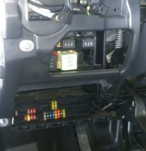
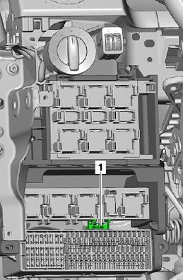
Above it is the main relay block. In some models it is attached directly to the fuse block. There may be a thermal fuse for the driver’s seat adjustment: 1 – 20A.
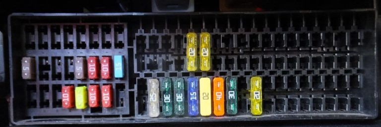
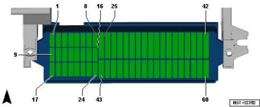
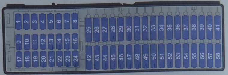
There are 2 different versions of the fuse block. They are similar in appearance, but differ in the number of elements – 58 and 60, respectively. The actual numbering will be printed on the block itself.
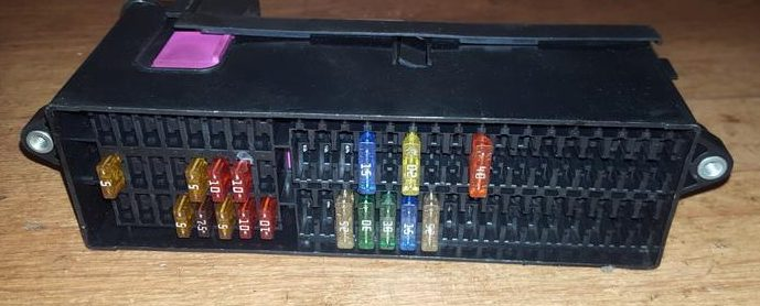
Option 1
Photo
Description
| 1 | 10A Control unit for access authorization and engine start system |
| 2 | 10A Control unit for access authorization and engine start system |
| 3 | |
| 4 | |
| 5 | |
| 6 | |
| 7 | |
| 8 | |
| 9 | 5A Airbag control unit and front passenger airbag deactivation indicator lamp |
| 10 | |
| 11 | |
| 12 | 10A Control unit for adaptive lighting and headlight range control system on the left |
| 13 | 5A /15A Parking assistant control unit, Climatronic control unit, Heater and mode selection switch, Supply fan relay, ASR and ESP off button and their indicator lamp, Tire pressure indicator button, Reversing light switch, Rearview mirror load sensor, Start-stop mode button |
| 14 | 10A/15A Diagnostic data bus interface, Instrument cluster control unit, Selector lever, Light switch, ASR and ESP off button, Tire pressure indicator button, Brake light switch, Multifunction switch, Tiptronic switch, Fuel pump control relay, ABS control unit, Starter relay, Trailer recognition control unit, Engine control unit |
| 15 | 10A Headlight range adjuster, Air flow meter, Crankcase ventilation system heating resistor, Supply fan relay, Selector sensor control unit, Adaptive lighting and headlight range adjuster control unit, Left headlight range adjuster actuator motor |
| 16 | 10A/15A Adaptive lighting and headlight range control unit on the right |
| 17 | 5A Instrument cluster control unit |
| 18 | 10A Mobile phone control electronics control unit |
| 19 | |
| 20 | 10A Selector lever, Climatronic control unit |
| 21 | 20A On-board network control unit, Rear left door control unit (central locking) |
| 22 | 10A Interior security system sensor, alarm siren |
| 23 | 10A Rear view camera control unit, Light switch, Rain and light sensor, diagnostic connector, Rear window heating relay, On-board network control unit |
| 24 | 10A Driver’s door control unit (central locking), Front passenger’s door control unit (central locking |
| 25 | |
| 26 | 20A Brake system vacuum pump |
| 27 | |
| 28 | |
| 29 | 20A Rear window wiper motor |
| 30 | 20A Cigarette lighter |
| 31 | |
| 32 | |
| 33 | 40A Supply fan relay |
| 34 | |
| 35 | |
| 36 | |
| 37 | |
| 38 | |
| 39 | |
| 40 | 15A Trailer recognition control unit |
| 41 | 15A Trailer recognition control unit |
| 42 | 20A Trailer recognition control unit |
| 43 | 30A Inverter with socket, 12 V – 230 V |
| 44 | 25A Rear window heating element, Supply fan relay |
| 45 | 30A Driver’s door control unit (power window), Front passenger’s door control unit (power window) |
| 46 | 30A Rear left door control unit (power window), Rear right door control unit (power window) |
| 47 | 15A Fuel pump and its relay |
| 48 | 20A On-board network control unit |
| 49 | 40A Supply fan control unit |
| 50 | 30A Front seat heating control unit |
| 51 | 20A Sliding sunroof control unit |
| 52 | 20A Headlight cleaning system relay |
| 53 | 15A Electric motor for longitudinal adjustment of lumbar support |
| 54 | 5A PDA control unit |
| 55 | |
| 56 | |
| 57 | 15A Main unit |
| 58 | |
| 59 | |
| 60 |
Fuse number 30 at 20A is responsible for the cigarette lighter.
Option 2
Photo example
Appointment
| Current consumer | Fuse number (next to it in brackets is the current in amperes) |
| Traction – coupling device | 2 (5), 39(15), 40(15), 41(20). |
| ABS | 14(5), 18(5) |
| Tilt sensor | 43 (5) |
| Braking signals | 13(10) |
| Brake light switch | 14(5) |
| Front window lifters | 45(30) |
| Rear window lifters | 46(30) |
| Fan | 33 (40) or 56 (40) |
| Heated rear window | 44(25) |
| Rear window wiper | 28(15) |
| Ultrasonics in the cabin | 43(5) |
| Fuel pump | 47(15) |
| Headlight leveling corrector | 3(5) |
| External socket | 53(15) |
| Parking sensors | 55(5) |
| Remote control | 4(5) |
| Rain sensor | 42(5) |
| Headlight washers | 52 (20) |
| Electric hatch | 51(25) |
| Seat heating | 13(5), 31(5), 50(30) |
| Fuel filler flap | 48(25) |
| Telephone | 10(5) |
| Central locking in the front doors | 24(10) |
| Central locking in the rear doors | 48(25) |
| Cigarette lighter | 49(25) |
| Rear socket | 54(20) |
| 230V socket | 37(30) |
Relay block
The number of relays in the unit, as well as the version, depends on the level of electrical equipment and year of manufacture.
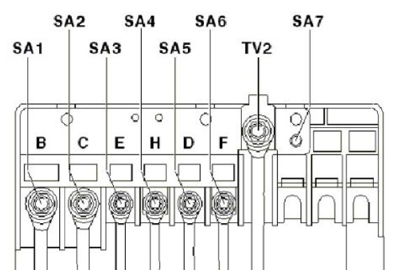
Scheme
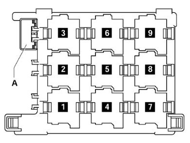
Transcript
- J496 – additional cooling system pump relay (449)
- J39 – headlight cleaning system relay (53)
- J17 – fuel pump relay (449) / J643 – fuel supply relay via the pressure line (449)
- J1З – supply fan relay (404)
- J333 – Fuel pump cut-off relay (404)
- not used
- J485 – relay for operation in auxiliary heater mode (449)
- J682 – power supply relay terminal 50 (433), from May 2006 (53)
- – not used
A – S44 thermal fuse 1 driver’s seat position adjustment 30 A
J17 and J643 are mini-relays and are installed (depending on the configuration) in one socket of the relay block.
Block on the hood
Located next to the battery and covered by a protective cover. Consists of 2 sections – fuses and high-power fuse links.
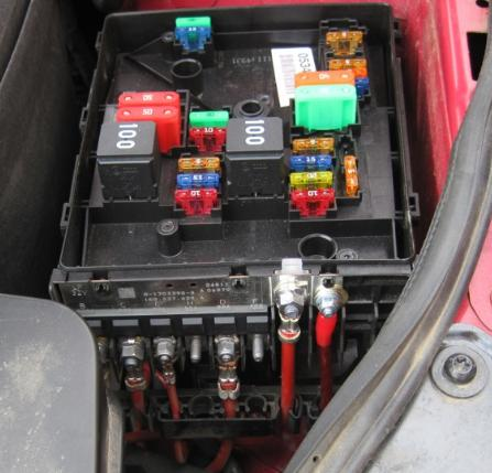
Fuse and relay compartment diagram
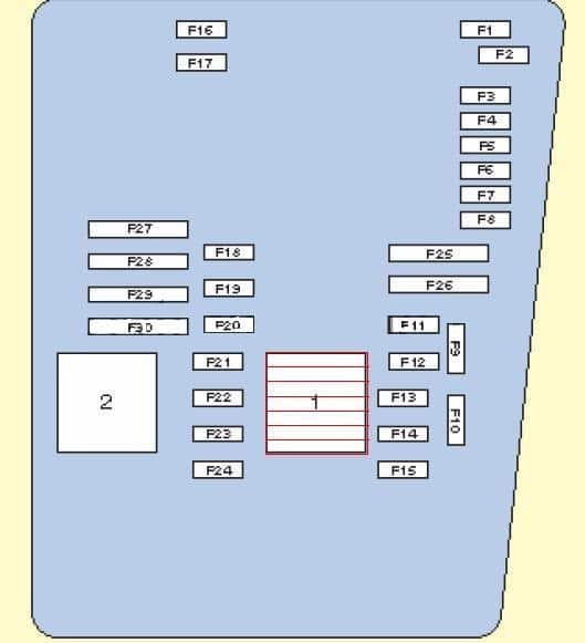
Appointment
| 1 | Engine control system relay |
| 2 | Exhaust air pump relay |
| F1 | (30A) Scum cleaner |
| F2 | (5A) Steering column electrical control unit / (30A) DSG gearbox Mechatronic unit |
| F3 | (5A) On-board network control unit |
| F4 | (30A) ABS electronic control unit |
| F5 | (15A) Electronic gearbox control unit |
| F6 | (5A) Instrument cluster |
| F7 | (40A) Power relay |
| F8 | (15A) Audio system / Head unit |
| F9 | (5A) Telephone control unit |
| F10 | (5A/10A) Electronic engine control unit |
| F11 | (20A) Auxiliary heater control unit |
| F12 | (5A) CAN data bus, gateway control unit |
| F13 | (15A/30A) Electronic engine control unit |
| F14 | (20A) Engine management system, Ignition coil |
| F15 | (5A/10A) Engine management system, Lambda sensor |
| F16 | (30A) ABS electronic control unit, Right headlight |
| F17 | (15A) Sound signal |
| F18 | (30A) Audio system |
| F19 | (30A) Windshield wiper/washer |
| F20 | (10A) Pump OJ |
| F21 | (10A/15A) Engine management system, Lambda probe, Electromagnetic clutch of the driven supercharger |
| F22 | (5A) Clutch pedal limit switch (position sensor) |
| F23 | (5A/10A/15A) Engine management system, Fuel pressure regulator, Secondary air pump relay |
| F24 | (10A) Engine management system, Exhaust gas recirculation valve, Solenoid valve |
| F25 | (40A) ABS control unit |
| F26 | (30A) Left headlight |
| F27 | (50A) Glow plug control unit |
| F28 | (40A) Main ignition circuits |
| F29 | (50A) Thermal fuse 1 seat adjustment |
| F30 | (40A) Starting system (50A) Contact relief relay X |
Fuse link diagram
- 150/200A – Generator
- 80A – Power steering
- 50A – Radiator fans
- 80A – High power heating relay
- 80A – Terminal connector 30, fuse block
- 40A – Low power heating relay
- 50A – Terminal connector 30, fuse block