Nissan Tiida is a compact car of the C-segment. The first generation C11 was produced in 2004, 2005, 2006, 2007, 2008, 2009 and 2010. The second generation C12 was produced in 2011, 2012, 2013 and 2014. From 2015 to the present, the third generation C13 has been on sale . Due to low demand for this model, official sales in Russia have been suspended. This article will provide information on the fuse boxes and relays in the Nissan Tiida with photographs, diagrams and a description of the purpose of their elements. We will also note the fuse responsible for the cigarette lighter.
Check the assignment of the fuses against the diagrams on the back of the protective cover.
In the salon
It is located in the instrument panel behind the protective cover on the driver’s side.
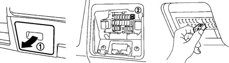
Option 1
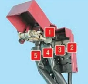
Photo – diagram
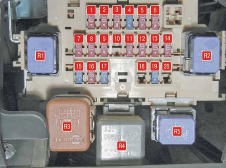
| 1 | 10A Passive safety system |
| 2 | 10A Additional interior equipment |
| 3 | 10A Instrument cluster |
| 4 | 15A Windscreen Washer Pump |
| 5 | 10A Heated exterior mirrors |
| 6 | 10A Electric mirrors, audio system head unit |
| 7 | 10A Brake lights |
| 8 | 10A Interior lighting |
| 9 | 10A Body electrical control unit |
| 10 | Reserve |
| 11 | 10A Right rear light marker lamp |
| 12 | 10A Left rear light marker lamp |
| 13 | 10A Instrument cluster |
| 14 | 10A Additional interior equipment |
| 15 | 15A Engine Cooling Fan Motor |
| 16 | 10A Heating, Air Conditioning and Ventilation System |
| 17 | 15A Engine Cooling Fan Motor |
| 18 | Reserve |
| 19 | 15A Socket for connecting additional equipment ( cigarette lighter ) |
| 20 | Reserve |
Fuse number 19, 15A, is responsible for the cigarette lighter.
Purpose of the relay
- R1 – Heater electric fan
- R2 – Additional equipment
- R3 – Relay (no data)
- R4 – Heated exterior mirrors
- R5 – Immobilizer
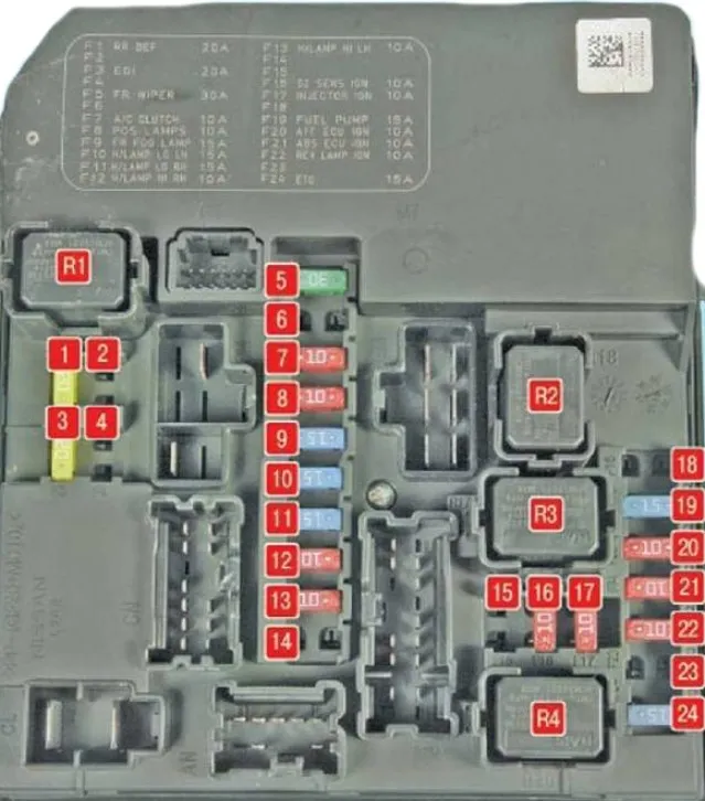
Option 2
Photo – diagram

- 10A Audio system, Audio-Acc mirror drive, power supply for swivel mirror motors, power supply for NATS (with chip key)
- 10A Rear window and side mirror heater
- 15A Front and rear window washer motor
- 10A Instrument cluster
- 10A Electronics
- 10A Airbag Module
- 10A Electronics
- –
- 10A Interior and trunk lighting
- –
- –
- 10A Stop lamps
- 10A Passive Entry (For systems with Chip Key)
- 10A Electronics
- 15A Socket – Cigarette Lighter
- 10A Seat heating
- 15A Outlet – Console, Trunk
- 15A Heater/Air Conditioner Fan
- 10A Air Conditioner
- 15A Heater/Air Conditioner Fan
Fuses 15 and 17, rated at 15A, are responsible for the cigarette lighter.
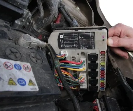
Under the hood
In the engine compartment next to the battery there are 2 blocks with fuses and relays, one additional relay block and on the positive terminal of the battery there are high-power fuse links.
Mounting block
Option 1
Scheme
| 1 | 20A Rear door glass heating |
| 2 | Reserve |
| 3 | 20A Engine Control Unit |
| 4 | Reserve |
| 5 | 30A Windscreen Washer |
| 6 | Reserve |
| 7 | 10A Air Conditioning Compressor Electromagnetic Clutch |
| 8 | 10A License Plate Lights |
| 9 | 15A Fuse for fog lights Nissan Tiida (in variant design) |
| 10 | 15A Low beam left headlight |
| 11 | 15A Right headlight low beam lamp |
| 12 | 10A Right headlight high beam lamp |
| 13 | 10A Left headlight high beam lamp |
| 14 | Reserve |
| 15 | Reserve |
| 16 | 10A Exhaust Gas Oxygen Sensors |
| 17 | 10 Injection system |
| 18 | Reserve |
| 19 | 15A Fuel Module |
| 20 | 10A Automatic transmission sensor |
| 21 | 10A ABS |
| 22 | 10A Reverse Light Switch |
| 23 | Reserve |
| 24 | 15A Additional equipment |
| R1 | Rear Window Heating Relay |
| R2 | Cooling system fan relay |
| R3 | Cooling system fan relay |
| R4 | Ignition system relay |
Option 2
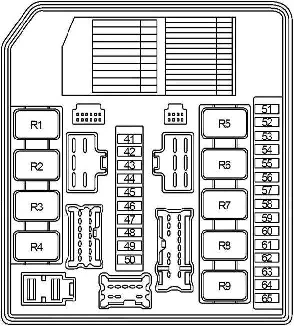
- 43 (10A) Front high beam headlight right
- 44 (10A) Left high beam headlight
- 45 (10A) Air conditioning, standard music lighting and right side lights, lighting, headlight adjustment motors
- 46 (10A) Parking lighting, Illumination of switches under seats, door opening
- 48 (20A) Windshield wiper motor
- 49 (15A) Left low beam headlight
- 50 (15A) Right low beam headlight
- 51 (10A) Air conditioning compressor
- 55 (15A) Rear window defroster
- 56 (15A) Rear window defroster
- 57 (15A) Gasoline pump (CH)
- 58 (10A) Power supply for automatic transmission systems (AT)
- 59 (10A) ABS control unit
- 60 (10A) Additional electrical
- 61 (20A) To terminal B+ IPDM, Throttle Motor and Relay (for CH)
- 62 (20A) To terminal B+ IPDM, to terminals ECM/PW and BATT of the ECM ©, terminal power supply of ignition coils, CKP sensor, DPRV, EVAP Canister valve, IVTC valve
- 63 (10A) Oxygen sensors
- 64 (10A) Injector coils, injection system
- 65 (20A) Front fog lights
- R1 – Rear window heating relay
- R2 – Main relay of the engine control unit
- R3 – Low beam headlight relay
- R4 – High beam relay
- R5 – Starter relay
- R6 – Engine cooling system fan 2 relay
- R7 – Engine cooling system fan 1 relay
- R8 – Engine cooling system fan 3 relay
- R9 – Ignition relay
Additional fuse box
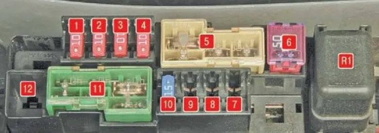
| 1 | 10A Immobilizer |
| 2 | 10A Seat heating |
| 3 | 10A Generator |
| 4 | 10A Sound signal |
| 5 | 60/30/30A Electric Power Steering Control Unit, Headlight Washer, ABS System |
| 6 | 50A Electric window lifter |
| 7 | Reserve |
| 8 | 15A Diesel engine injection system |
| 9 | 10A Throttle Assembly |
| 10 | 15A Head unit audio systems |
| 11 | 40/40/40A ABS system. Body electrical equipment control unit, ignition system |
| 12 | Reserve |
| R1 | Horn relay |
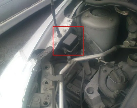
Additional relay block
It is located on the right side. It is possible to install 2 relays, for example, windshield wipers and daytime lighting. Depending on the configuration, they may also be empty.
Fuses on the battery terminal
Scheme
Designation
- 120A Electric Power Steering Control Unit, Headlight Washer, ABS System
- 60A Engine Control Unit, Throttle Relay, Electric Window Relay
- 80A Low and high beam headlights
- 80A Immobilizer, seat heating, generator, horn
- 100A ABS system, body electrical equipment control unit, ignition system, electric power steering control unit, headlight washer