Peugeot 307 was produced in 2001, 2002, 2003, 2004, 2005, 2006, 2007, 2008, 2009, 2010 and 2011 with body variants sedan, hatchback, hatchback. This material shows where the fuse blocks of the Peugeot 307 are located, their diagrams and description in Russian, the fuse responsible for the cigarette lighter is highlighted.
The Peugeot 307 has several possible fuse block designs, and they depend on the year of manufacture of the car.
Option 1
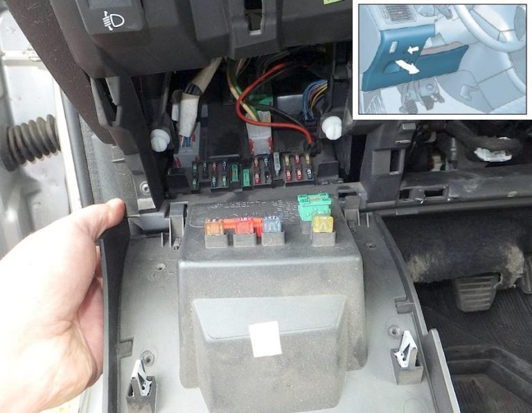
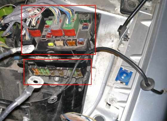
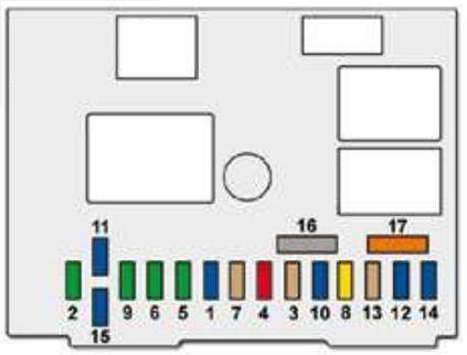
Fuses in the passenger compartment
For access, you must remove the protective cover.
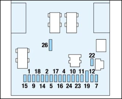
Description
| 1 | 10A Rear fog light. |
| 2 | 15A Rear wiper. |
| 4 | 15A Front windows Ventilation hatch. |
| 5 | 15A Left brake light, including trailer brake light. |
| 7 | 20A Rear lamp, front lamp, local lighting lamp, cigarette lighter, glove box lighting. |
| 9 | 30A Power window buttons, one-touch power window buttons (not suitable for non-one-touch), ventilation hatch button. |
| 10 | 15A Diagnostic connector, rear electrical socket 12 V. |
| 11 | 15A Car radio, multifunction display, steering wheel switches, automatic transmission electronic control unit. |
| 12 | 10A Front right and rear right side lights, car and trailer license plate light, remote lock control unit, security alarm, ESP, hazard warning lights, ashtray and air conditioning control panel lighting, electric seat heating, cigarette lighter, headlight regulator unit contactor. |
| 14 | 30A Locking/full locking of locks, superlock drive. |
| 15 | 30A Rear windows. |
| 16 | 5A Engine switch unit, security alarm, particulate filter, steering wheel switches, airbags. |
| 17 | 10A Rear right brake light, additional brake light. |
| 18 | 10A Diagnostic connector, steering wheel switches, brake light switch and clutch sensor, coolant level sensor, 2nd brake system sensor. |
| 19 | 30A Shunt PARC. |
| 22 | 10A Front left and rear left side marker lights, vehicle and trailer license plate light. |
| 23 | 15A Security alarm siren, interior volume sensor. |
| 24 | 15A Instrument panel, car radio, multifunction display, air conditioner. |
| 26 | 30A Electric rear window heater. |
Fuse number 7 is responsible for the front cigarette lighter, and fuse number 9 is responsible for the rear cigarette lighter.
Block under the hood
The block can be conditionally divided into two parts.
General diagram of the upper part
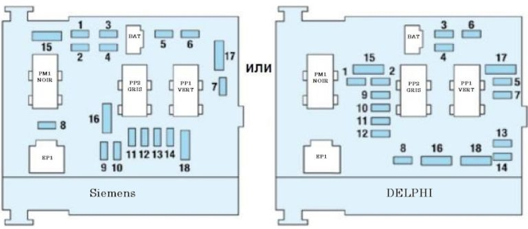
Marking
- 10A Automatic gearbox reverse light switch, automatic gearbox lock relay, manual gearbox reverse light switch, speed sensor, glow plug power supply unit, water in diesel fuel sensor, DW air flow meter.
- 15A Fuel vapor absorber solenoid valve, fuel pump.
- 10A Electronic power steering control unit, ABS or ESP electronic unit.
- 10A Injection computer, engine cooling fan group relay, additional heating system relay, automatic transmission electronic unit, automatic transmission gear shifting electronic control unit, automatic transmission shift lock relay.
- 15A Diesel particulate filter sensor.
- 15A Front fog lights.
- 20A Headlight washer pump motor.
- 20A Engine cooling fan group relay, injection computer power supply circuit.
- 15A Left dipped beam headlight.
- 15A Right dipped beam headlight.
- 10A Left high beam headlight.
- 10A Right high beam headlight.
- 15A Audible signal.
- 10A Windshield and rear window washer pump motors.
- 30A Oxygen sensors, exhaust gas recirculation system solenoid valve, ignition coil, diesel engine fuel system high pressure regulator, injector power supply circuit.
- 40A Solenoid valve for regulating the boost pressure of the power unit with automatic transmission.
- 30A Relay for normal and accelerated windscreen wiper operation modes.
- 40A Air conditioning system electric motor.
Purpose of the lower fuses
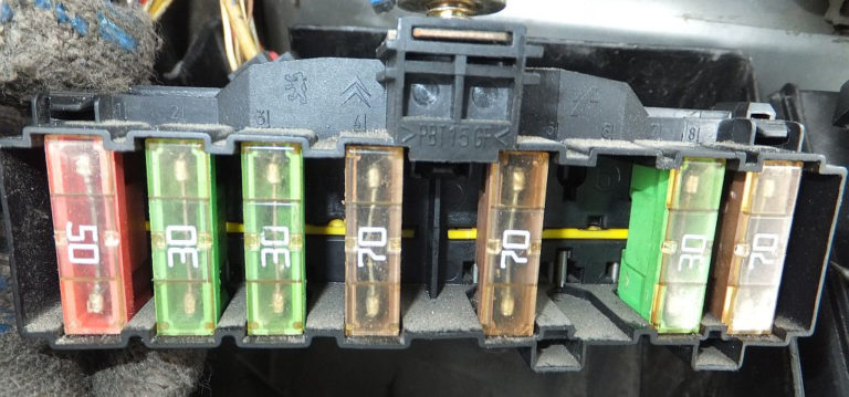
| 1 | 30/50A Engine cooling fan group. |
| 2 | 30A ESP/ABS system pump motor. |
| 3 | 30A ESP/ABS system solenoid valves. |
| 4 | 60/70A Power supply circuit of the intelligent control unit for switching on-board systems. |
| 5 | 70A Power supply circuit of the intelligent control unit for switching on-board systems. |
| 6 | 20A Electric seat heating. |
| 7 | 30A Ignition lock with anti-theft system, power supply circuit. |
| 8 | 70A Power steering pump motor. |
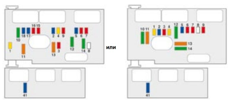
Option 2
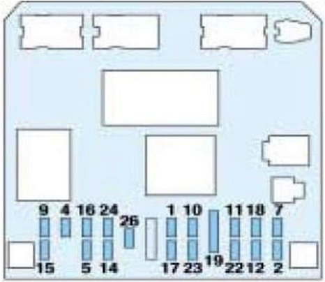
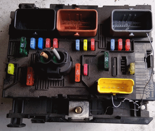
Fuses in the passenger compartment
Photo – example of execution
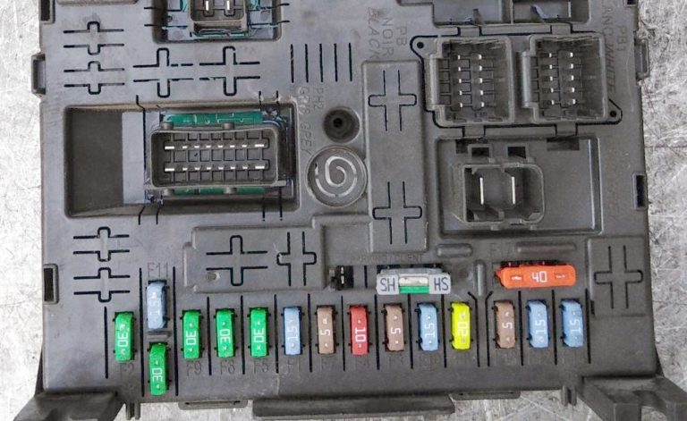
Transcript
- F1 15 A Rear wiper.
- F2 30 A Locking and superlocking system.
- F3 5 A Airbag and pyrotechnic tensioner system unit.
- F4 10 A Brake (brake light) and clutch pedal contactor, coolant level sensor, crankshaft position sensor, ESP system sensor, particulate filter additive pump, diagnostic connector, photosensitive rearview mirror.
- F5 30 A Front electric windows, sunroof, heated mirrors.
- F6 30 A Rear power windows.
- F7 5 A Rear and front lights, individual lighting lights, glove box lighting.
- F8 20 A Car radio, radio telephone, multifunction display, alarm siren, electronic alarm unit, trailer switching unit, training vehicle module, steering column switch unit.
- F9 30 A 12 V socket front, 12 V socket rear.
- F10 15 A Automatic transmission computer, tire pressure drop system computer, brake light contactor.
- F11 15 A Diagnostic connector, particulate filter unit, ignition switch low current circuit.
- F12 15 A Driving school module, parking system parking sensors.
- F13 5 A Engine switch unit, rain and light sensor.
- F14 15 A Trailer switchboard, instrument panel, electronic airbag and pyrotechnic tensioner control unit, automatic air conditioning, hands-free headset.
- F15 30 A Locking and superlocking of locks.
- F16 – Shunt PARC.
- F17 40 A Heated rear window.
- F39 20 A Heated driver and passenger seats.
Fuse number 9 at 30A is responsible for the rear and front cigarette lighter.
Block under the hood
Purpose of elements
- 20 A Power supply for the engine computer and the high-speed relay for the cooling system fan.
- 15 A Sound signal.
- 10 A Front and rear window washers.
- 20 A Headlight washer.
- 15 A Fuel pump and adsorber solenoid valve (on 2.0 liter gasoline engine).
- 10 A Four-speed automatic transmission processor, automatic transmission selector lever lock switch, power window switch, high-speed cooling fan relay, left and right xenon headlights.
- 10 A ABS/ESP computer, power steering computer.
- 25 A Ignition switch, starter switch.
- 10 A Auxiliary heating unit (Diesel), coolant level sensor.
- F10 30 A Components of the electronic engine control system (ignition coil, solenoid valves, oxygen sensors, computers, injectors, glow plugs), adsorber solenoid valve (on 1.4 l and 1.6 l gasoline engines).
- 40 A Air conditioning fan.
- 30 A Windscreen wiper low/high speed.
- 40 A Power supply for the intelligent switching unit (+ after the ignition switch).
- 30 A Compressor (2L petrol engines).
- 10 A Right high beam headlight.
- 10 A Left high beam headlight.
- 15 A Left dipped beam headlight.
- 15 A Right dipped beam headlight.
Separately located F41 – 15 A. Processor of the six-speed automatic transmission. High-power fuses (maxi) are located in the lower part of the block.
Description of maxi fuses (MF)
MF1 30 A Cooling system fan 200 W. / 50 A Cooling system fan 400 W and 460 W.
MF2 30 A ABS/ESP system pump.
MF3 30 A ABS/ESP solenoid valves.
MF4 80 A Intelligent switching unit power supply.
MF5 80 A Intelligent switching unit power supply.
MF6 80 A Passenger compartment fuse box.
MF8 70 A Power steering pump.
Individual relay elements can be installed outside these blocks.