Chevrolet Spark is a small-capacity city car of class A. The model was developed by the South Korean division of General Motors (Daewoo) and presented in 2005. This is the smallest car among the manufacturer’s models. In this material, we will examine in detail the fuse diagrams of the second-generation Chevrolet Spark ( M200 ) of 2006, 2007, 2008, 2009, 2010 release.
Here you will find the locations and photos of the mounting blocks. We will separately note the fuses responsible for the cigarette lighter and fuel pump.
In the salon
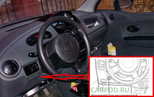
The unit is located on the driver’s side, at the bottom of the dashboard.
To access it, you need to squeeze the latches and remove the cover.
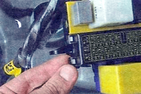
General view of the block.
| Chevrolet Spark Cabin Block Diagram |
|---|
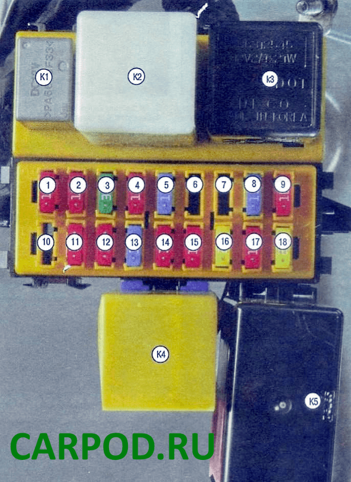
| No. | Transcript | Current, A |
| 1 | Instrument cluster, indicator lamp unit, brake lights, anti-theft alarm control unit, overdrive switch (for vehicles with automatic transmission) | 10 |
| 2 | Engine management system | 10 |
| 3 | Electric windows | 30 |
| 4 | Hazard warning switch, speed alarm relay (for vehicles with automatic transmission) | 10 |
| 5 | Engine Compartment Fuse Box Circuit | 15 |
| 6 | Spare | — |
| 7 | Spare | — |
| 8 | Spark cigarette lighter fuse | 15 |
| 9 | Audio system | 10 |
| 10 | Spare | — |
| 11 | Engine management system diagnostic connector, indicator lamp unit, immobilizer | 10 |
| 12 | Audio system, interior lighting | 10 |
| 13 | Door lock relay, door lock switch, anti-theft system unit | 15 |
| 14 | Brake light switch circuit | 10 |
| 15 | Rear door glass wiper, rear door glass heater circuit | 10 |
| 16 | Windscreen wiper | 20 |
| 17 | Range selector switch (on vehicles with automatic transmission), reversing light switch (on vehicles with manual transmission) | 10 |
| 18 | Fan motor | 20 |
| Purpose of relay modules | ||
| K1 | Rear door glass heater relay | |
| K2 | Security alarm relay | |
| KZ | Direction indicator relay | |
| K4 | Rear Fog Light Relay | |
| K5 | Direction indicator relay | |
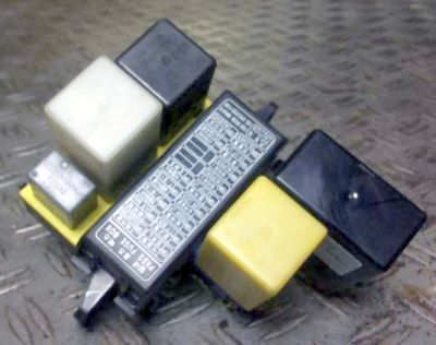
In the engine compartment
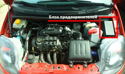
Located on the left side of the engine compartment.
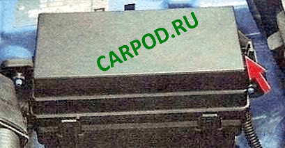
To access the fuses, you need to press the latch and remove the protective cover.
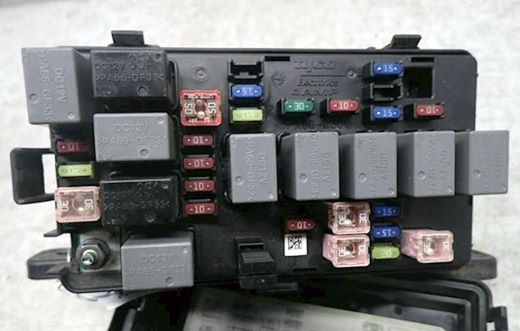
General view of the mounting block.
| Underhood block diagram |
|---|
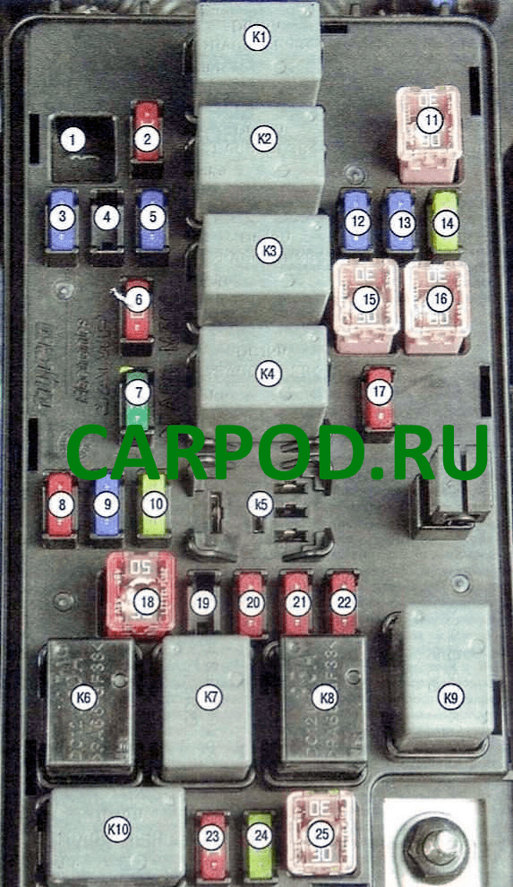
| No. | Description | Current, A |
| 1 | Spare | — |
| 2 | Automatic transmission electronic control unit, engine control system electronic unit | 10 |
| 3 | Engine management system, injectors, rough road sensor, exhaust gas recirculation valve, oxygen sensor, camshaft position sensor, canister purge valve | 15 |
| 4 | Spare | — |
| 5 | High beam headlight relay | 15 |
| 6 | Low beam headlights | 10 |
| 7 | Spare | — |
| 8 | Spare | — |
| 9 | Spare | — |
| 10 | Spare | — |
| 11 | Ignition switch chain | 30 |
| 12 | Fuel module (fuel pump) | 15 |
| 13 | Hazard warning switch circuit | 15 |
| 14 | Rear Door Glass Defroster Relay Circuit | 20 |
| 15 | Under Dash Fuse Box Circuit | 30 |
| 16 | Ignition switch chain | 30 |
| 17 | Low beam headlights, rear fog light relay circuit, headlight switch circuit | 10 |
| 18 | Hydroelectronic ABS module | 50 |
| 19 | Front fog light circuit | 10 |
| 20 | Horn circuit | 10 |
| 21 | Radio, hazard warning lights, air conditioning circuit, automatic transmission range selector light, instrument cluster | 10 |
| 22 | Side lights, electric headlight range adjuster | 10 |
| 23 | A/C Compressor Relay Circuit | 10 |
| 24 | Engine Cooling Fan Motor Low Speed Relay Circuit | 20 |
| 25 | Engine Cooling Fan Motor High Speed Relay Circuit | 30 |
| No. | Purpose of the relay | |
| K1 | Fuel pump relay (fuel pump) | |
| K2 | High beam headlight relay | |
| KZ | Low beam headlight relay | |
| K4 | Horn relay | |
| K5 | Fog light relay | |
| K6 | Main relay | |
| K7 | Engine Cooling Fan Motor Low Speed Relay | |
| K8 | Engine Cooling Fan Motor High Speed Relay | |
| K9 | Parking light relay | |
| K10 | Air Conditioning Compressor Relay |