Hyundai H1 (GRAND STAREX) is a minivan with a wide range of applications, produced since 1996 to the present day in 2 generations as a van or minibus. In this material you will find a description of the fuses and relays of the Hyundai Grand Starex h1 with diagrams and photos of the blocks for the 2nd generation of the model, produced in 2007, 2008, 2009, 2010, 2011, 2012, 2013, 2014, 2 9 , 2020, 2021, 2022. Let’s highlight the fuse responsible for the cigarette lighter.

During this production period, the Hyundai H1 (Grand Starex) underwent restyling, so the purpose of the elements in the blocks may differ and depend on the year of manufacture, equipment level and region of delivery. Compare the description with your diagrams on the back of the protective cover.
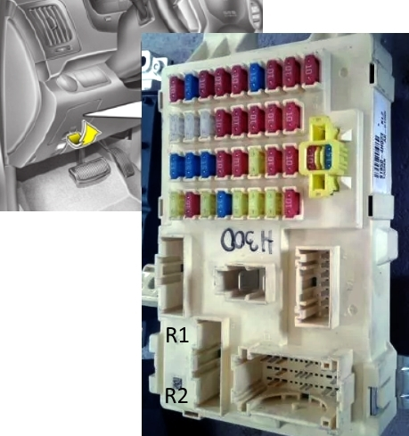
Cabin block
It is located at the bottom of the instrument panel (driver’s side), behind a cover.

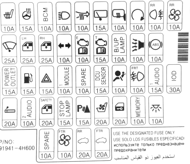
Fuse description
| AUDIO-2 | 10A Audio, digital clock, BCM, outside mirror switch with power |
| C/ LIGHTER | 20A Cigarette Lighter, Front Socket |
| S/HTD DRI | 10A Driver’s seat heater switch (if equipped) |
| DRL | 10A BCM (if available) |
| RR FOG LP | 10A Rear fog light relay |
| H/LP | 10A Headlight high/low beam relay |
| FRT WIPER | 25A Front wiper relay, front wiper motor |
| BCM | 10А BCM |
| HTR | 10A Front/Rear Fan Relay, Front/Rear A/C Control Module, Condenser Fan Relay, Electro Chrome Mirror, Thermal Switch, PTC Heater Relay (D4CB), EGR Solenoid Valve (D4BH) |
| B/UP LP | 10A Reverse light relay, reverse light switch, transmission range switch |
| ABS | 40A ABS/ESP control unit, ESP switch (D4CB) |
| T/SIG LP | 10A Turn signal switch |
| A/BAG | 10A SRS control module |
| A/BAG IND | 10A Instrument panel (indication) |
| MODULE | 10A Instrument cluster, BCM, Immobilizer control module (D4BH), Air conditioner relay (D4BH), Alternator resistor |
| ECU | 10A Vehicle speed sensor, ECM, air flow sensor (D4CB), fuel pump (D4BH), TCM, fuel filter warning sensor |
| START | 10A Start relay, security alarm relay |
| MIRR HTD | 10A Front air conditioning control module, power exterior mirror and left/right window heater |
| STOP LP | 15A Stop signal switch |
| BUS | 10A Buzzer |
| DR LOCK | 20A Door lock/unlock relay |
| FRT FOG LP | 10A Front fog light relay |
| B/ALARM | 10A Burglar Alarm Sounder Relay |
| AUDIO-1 (POWER CONNECTOR) | 15A Audio |
| ROOM LP (POWER CONNECTOR) | 10A Digital clock, Instrument cluster, LH/RH illumination, LH/RH footrest, Luggage compartment lamp, Interior light switch, Door alarm switch, Data link connector, BCM, LH/RH vanity light switch, Overhead console illumination |
| HAZARD | 15A Hazard warning relay, emergency switch |
| FUEL LID | 15A Fuel filler flap relay |
| P/WDW LH | 25A Electric lift main switch, electric lift switch, left |
| P/WDW RH | 25A Main power window switch, right power window switch |
The front cigarette lighter is marked C/ LIGHTER, and the rear POWER OUTLET.
Relay decoding
- R1 – electric window lifter relay
- R2 – fuel filler flap relay
Also, the following non-removable relays can be attached to the back: rear fan relay, rear light relay, front fan relay, rear window heater relay.
Option 2
Scheme
Blocks under the hood
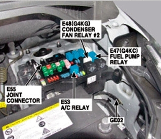
Main unit
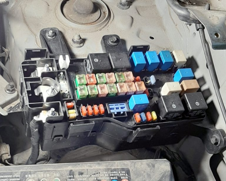
Located on the left side of the engine compartment, next to the battery.
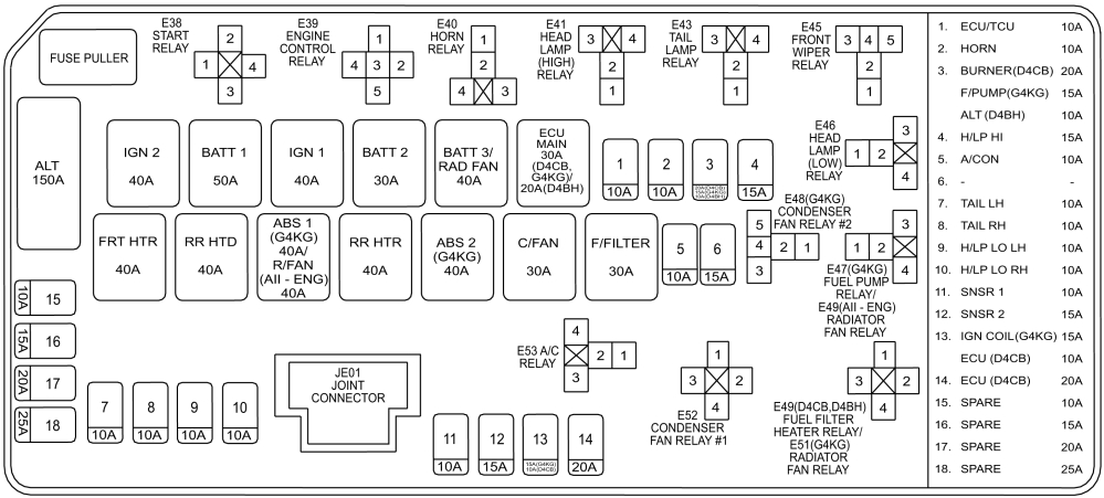
Appointment
| ALL | 150A Fuse (A/CON, FRT DEICER), fuse link (FRT HTR, RR HTR, RR HTD, C/FAN, F/FILTER, ABS 1/2), alternator, fuse block and relay E/R, right |
| BATT1 | 50A Fuse (DR LOCK, FRT FOG LP, B/ALARM, power connector (AUDIO-1, ROOM LP)) |
| BATT2 | 30A Fuse (FUEL LID, P/WDW LH/RH, HAZARD), multi-purpose control connector |
| BATTERY 3/ROW FAN | 40A Fuse (STOP LP, BWS), Radiator Fan Relay (G4KC) |
| IGN 1 | 40A Ignition switch (ACC, IG1) |
| IGN 2 | 40A Ignition switch (IG2, START), starting relay |
| ECU MAIN | 20/30A Engine Control Relay |
| FRT HTR | 40A Front fan relay |
| RR HTD | 40A Rear window defroster relay |
| RR HTR | 40A Rear fan relay |
| ABS 1 | 40A ABS control module (G4KC) |
| ABS 2 | 40A ABS control module (G4KC) |
| C/FAN | 30A Condenser Fan Relay 1 |
| F/FILTER | 30A Fuel filter heater relay (DIESEL) |
| ECU/TCU | 10A TCM, ECM (petrol) |
| HORN | 10A Horn Relay |
| BURNER | 20A Fuel Heater Control Module (D4CB) |
| F/PUMP | 15A Fuel Pump Relay (G4KC) |
| ALL | 10A Generator (D4BH) |
| H/LP HI | 15A Headlight relay (HIGH), headlight relay (LOW) |
| A/CON | 10A Air conditioner relay |
| FRT DEICER | 15A Windshield defroster relay (if equipped) |
| TAIL LH | 10A Left headlight (sidelight), Left rear combination lamp, Left sidelight |
| TAIL RH | 10A Right headlight (sidelight), right rear combination light, right sidelight |
| H/LP LO LH | 10A Left headlight |
| H/LP LO RH | 10A Headlight right |
| SNSR 1 | 10A Air conditioner relay, condenser fan relay (D4CB), lambda sensor (D4CB), heater PTC relay #1 (D4CB), brake light switch (D4CB) |
| SNSR2 | 15A D4CB: camshaft position sensor, glow plug relay, exhaust gas recirculation actuator, VGT control valve, immobilizer control module G4KC: fuel pump relay, adsorber purge solenoid valve, oil control valve, crankshaft position sensor, immobilizer control module, idle speed control actuator |
| IGN COIL | 15A Ignition coil #1~#4 (G4KC), capacitor (G4KC) |
| ECU 1 | 10А ECM (D4CB) |
| ECU 2 | 20A ECM (D4CB, G4KC), injector #1 ~ #4 (G4KC) |
| SAFETY P/WDW | 20A Glass safety lift |
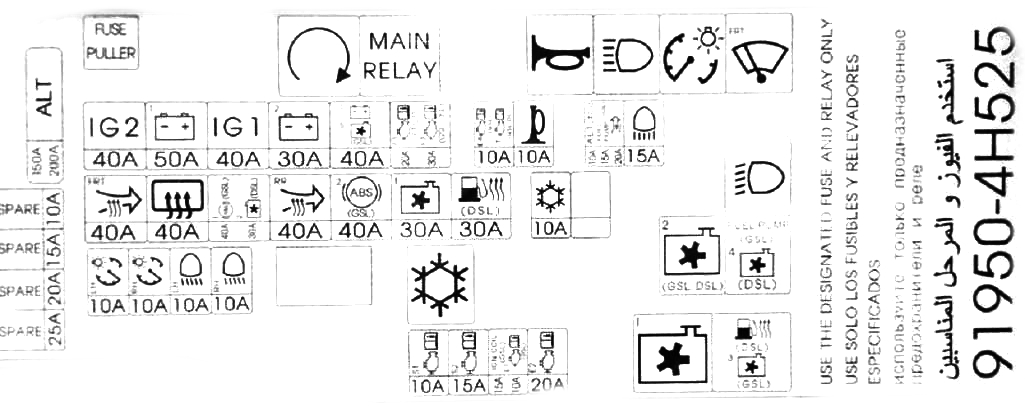
Scheme option 2
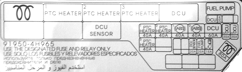
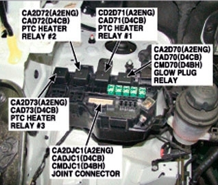
Additional unit
It is installed mainly on diesel models, on the right, next to the rack.
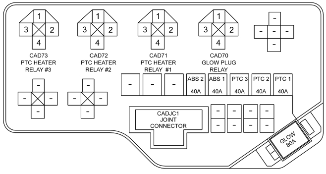
Marking
| GLOW | 80A Glow plug relay |
| PTC HEATER 1 | 40A PTC Heater Relay #1 |
| PTC HEATER 2 | 40A PTC Heater Relay No. 2 |
| PTC HEATER 3 | 40A PTC Heater Relay #3 |
| ABS 1 | 40A ABS/ESC control unit |
| ABS 2 | 40A ABS/ESC control unit |
| ECU | 15A Electronic control unit power supply |
| FUEL PUMP | 20A Fuel pump motor |
| DCU 1 | 20A Power of the dosing control unit 1 |
| DCU 2 | 20A Power 2 dosing control unit |
| DCU 3 | 20A Power 3 dosing control unit |
| DCU | 60A Main power supply for dosing control unit |
Scheme option 2