Opel Corsa D (opel corsa d) is the fourth generation of one of the most popular Corsa series. Years of production: 2006, 2007, 2008, 2009, 2010, 2011, 2012, 2013 and 2014. During this time, the car was restyled once. In this article, you will find a description of the fuse boxes and relays of the Opel Corsa D with block diagrams, their locations and photographs. We will highlight the fuse responsible for the cigarette lighter. At the end, we will offer for downloading a complete repair manual for the opel corsa d.
The design of the fuse and relay boxes may differ from that shown and depends on the year of manufacture and country of delivery of your Opel Corsa D.
Blocks under the hood
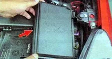
Mounting block
It is located on the left side next to the battery and is covered with a protective cover, on the back of which is the current diagram.
Option 1
Photo – diagram
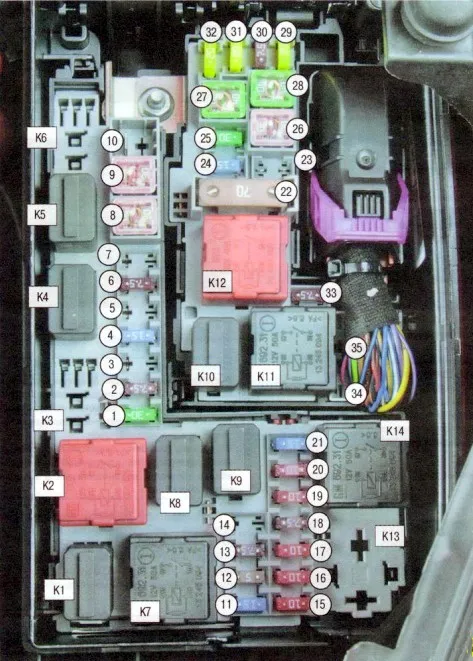
Description
| 1 | 30A Starter |
| 2 | 7.5A Air Conditioner |
| 3 | 15/30A Heating of the diesel fuel system |
| 4 | 15A Sound signal |
| 5 | 15A Easytronic, automatic transmission |
| 6 | 7.5A Engine Control Unit |
| 7 | 15A Fog lights |
| 8 | 30/40A Engine cooling |
| 9 | 30/40/60A Engine cooling |
| 10 | 30/60A Easytronic, gearbox |
| 11 | 7.5/15A Glow plugs, ignition system |
| 12 | 5A External lighting control unit, headlight range adjustment, adaptive light system |
| 13 | 7.5A Heater, air conditioner |
| 14 | 5A Easytronic, automatic transmission |
| 15 | 10A High beam, adaptive lighting right |
| 16 | 10A High beam, adaptive lighting left |
| 17 | 10A Main Fuses |
| 18 | 7.5A Electronic Engine Control Unit |
| 19 | 10A Airbag |
| 20 | 10A Main Fuses |
| 21 | 15/20A Main fuses |
| 22 | 70A Central control unit of the vehicle electrical equipment |
| 23 | 20A Compressor, Tyre Repair Kit |
| 24 | 15A Fuel pump |
| 25 | 30A Electronic control unit for anti-lock braking system |
| 26 | 30A Rear window heating |
| 27 | 30A ABS |
| 28 | 30A Electric cabin fan (air conditioning, climate control) |
| 29 | 20A Cigarette Lighter Fuse |
| 30 | 7.5A Air conditioner, climate control |
| 31 | 20A Left window lifting mechanism |
| 32 | 20A Right window lifting mechanism |
| 33 | 7.5A Heated exterior mirrors |
| 34 | Reserve |
| 35 | Reserve |
| K1 | Horn relay |
| K2 | Ignition relay (ignition switch unloading relay), terminal “15” |
| KZ | Filter heating relay |
| K4 | High beam headlight relay |
| K5 | Air conditioning compressor relay |
| Kb | Front fog light relay |
| K7 | Radiator Fan Relay |
| K8 | Electronic Engine Control Unit Relay |
| K9 | Starter relay |
| K10 | Fuel pump relay |
| K11 | Ignition relay (ignition switch unloading relay), terminal “15” |
| K12 | Rear door glass heating relay |
| K13 | Radiator Fan Relay |
| K14 | Radiator Fan Relay |
Fuse number 29 for 20A is responsible for the operation of the cigarette lighter.
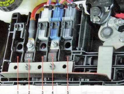
Option 2
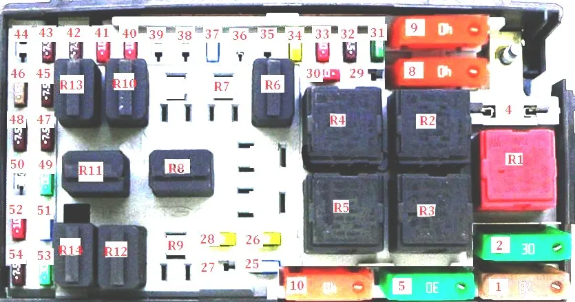
Designation
| R1 | Rear window heating relay |
| R2 | |
| R3 | |
| R4 | |
| R5 | |
| R6 | Engine Control Relay (EC) |
| R7 | Signal relay |
| R8 | Starter relay |
| R9 | Fuel heater relay |
| R10 | High beam headlight |
| R11 | |
| R12 | Front Fog Light Relay |
| R13 | Air Conditioning Compressor Clutch Relay |
| R14 | Fuel Pump Relay (FP) |
| 1 | 60A |
| 2 | 30A Rear window heating |
| 4 | 30A ASM transmission |
| 5 | 40A AC / Heating System |
| 8 | 60A Cooling Fan Motor |
| 9 | 50A Engine Coolant Fan Motor |
| 10 | 40A Anti-lock Brake System (ABS) |
| 25 | 15A Front fog lights |
| 26 | 20A Electric Windows |
| 27 | 30A |
| 28 | 20A Electric Windows |
| 29 | Reserve |
| 30 | 20A Motor Control |
| 31 | 30A |
| 32 | 7.5A Engine Control |
| 33 | 15A Engine Control |
| 34 | 15A Engine Control |
| 35 | Reserve |
| 36 | 15A Automatic transmission (AT) |
| 37 | 15A Signal |
| 38 | Reserve |
| 39 | Reserve |
| 40 | 10A High beam left |
| 41 | 10A High beam headlight, right |
| 42 | 10A AC Compressor Clutch |
| 43 | 10A Heated Mirrors |
| 44 | Reserve |
| 45 | 15A Engine Control |
| 46 | 10A Headlamp Aiming Control Module |
| 47 | 7.5A Engine Control |
| 48 | 7.5A AC / heating system |
| 49 | 30A Starter |
| 50 | 15A |
| 51 | 15A Fuel Pump (FP) |
| 52 | 20A SRS Control Module |
| 53 | 30A Anti-lock Braking System (ABS) |
| 54 | 7.5A AC / heating system |
Battery powered block
This unit is attached to the battery cover and consists of high-power fuse links.
Scheme
- 80A Used for diesel engines
- 80A Electric Power Steering
- 60A Additional and independent heater
- 50A Power supply for the mounting block located in the trunk
- 40A Additional and independent heater
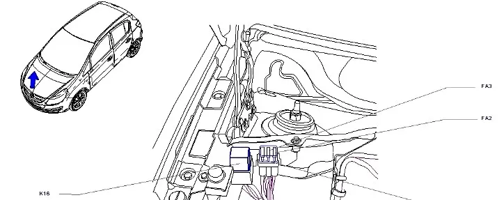
Additional relays
Depending on the configuration, individual relay elements may be located outside the block, for example:
- k16 – fan relay
- FA1 – air conditioner
- FA2 / FA3 – heating
Block in the cabin
This unit is located under the instrument panel, behind the protective cover.
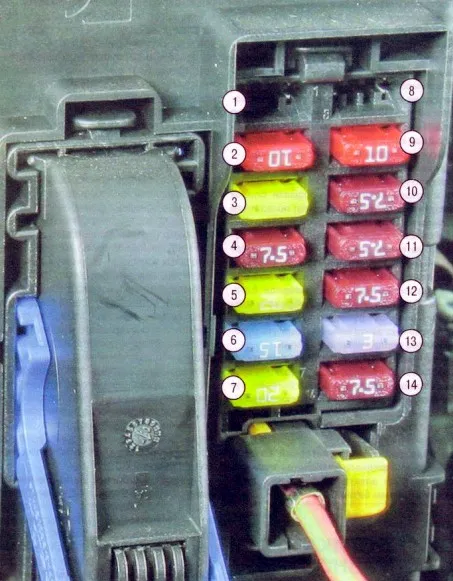
Purpose
| 1 | Reserve |
| 2 | 10A Instruments, information display |
| 3 | 20A Radio receiver |
| 4 | 7.5A Ignition switch |
| 5 | 20A Windscreen Wiper |
| 6 | 15A Central locking of the rear door (trunk) |
| 7 | 20A Central locking of side doors |
| 8 | Reserve |
| 9 | 10A Interior lighting |
| 10 | 7.5A Electric Power Steering |
| 11 | 7.5A External Lighting Control Unit, Brake Light, Clutch Switch |
| 12 | 7.5A ABS, brake light |
| 13 | 3A Heated Steering Wheel |
| 14 | 7.5A Rear Bicycle Rack, Parking System, Rain Sensor, Interior Mirror, Switch Block (on Center Console) |
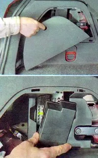
Block in the trunk
It is located on the stand on the left and is covered with a protective cover.
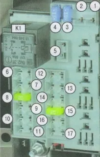
| 1 | 15A Adaptive Headlight System |
| 2 | Reserve |
| 3 | 15A Left seat heating |
| 4 | 15A Right seat heating |
| 5 | Reserve |
| 6 | Reserve |
| 7 | Reserve |
| 8 | 20A Flex-Fix system, towing hitch |
| 9 | Reserve |
| 10 | Reserve |
| 11 | Reserve |
| 12 | Reserve |
| 13 | Reserve |
| 14 | Reserve |
| 15 | 20A Flex-Fix system, towing hitch |
| 16 | Reserve |
| 17 | 20A Sliding roof |
| K1 | Ignition relay (ignition switch unloading relay) terminal “15a” |