General Motors presented the Chevrolet Volt concept car at the North American International Auto Show in 2007. Sales of the production model began in late 2010, and its identical versions in the concern’s lineup were the Opel Ampera, Vauxhall Ampera, Buick Velite 5 and Holden Volt , which had slight differences depending on the sales market. In this article, we will examine in detail the fuse diagrams of the first-generation Chevrolet Volt of 2010, 2011, 2012, 2013, 2014, 2015 release.

Here you will find the locations and photos of the mounting blocks. We will separately note the fuses responsible for the cigarette lighter and fuel pump.
In the engine compartment
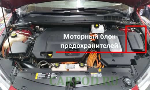
The mounting block is located on the driver’s side behind the protective cover.
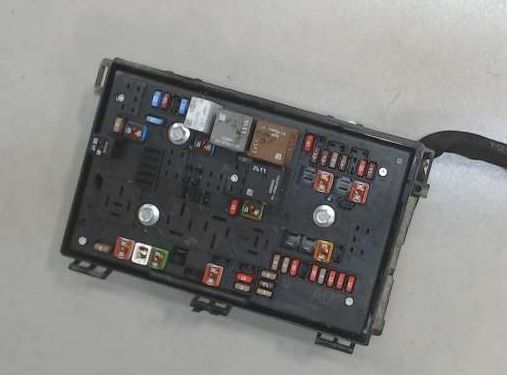
General view.
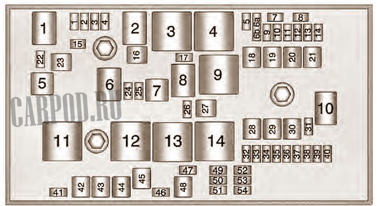
| No. | Type “Mini” | Current, A |
| 1 | Engine Control Module – Switchable Power | 15 |
| 2 | Exhaust system / CO2 sensor | 10/7.5 |
| 3 | Reserve | 10 |
| 4 | Ignition coils / injectors | 15 |
| 5 | Ignition switch | 10 |
| 6a | ||
| 6b | Rear anti-fog | 10/7.5 |
| 7 | Empty | – |
| 8 | Empty | – |
| 9 | Heated mirrors | 10/7.5 |
| 10 | Air Conditioning Control Module | 5 |
| 11 | Traction inverter module – battery | 10/7.5 |
| 12 | 2011: G36 – Auxiliary Heater Coolant Pump, Q66 Passenger Compartment Heater Coolant Control Valve | 15 |
| 13 | 2012-2015: G36 – Auxiliary Heater Coolant Pump, Q66 – Passenger Compartment Heater Coolant Control Valve | 7.5/10 |
| 14 | Emergency alarm – Sounder ( if available ) | 10/7.5 |
| 15 | Traction inverter module and transmission control module | 15 |
| 17 | Engine Control Module – Battery | 5 |
| 22 | Left headlight – high beam | 5 |
| 24 | Empty | – |
| 25 | Empty | – |
| 26 | Hazard warning lights – sound signal (if available) | 10 |
| 31 | — | |
| 32 | diagnostic module, instrument cluster, passenger airbag display, headlight leveling switch, auto-dimming interior rearview mirror (if equipped) | 5 |
| 33 | K27 Fuel Pump Control Module,K114B Hybrid Powertrain Control Module 2 | 5 |
| 34 | VICM – K114B Hybrid Powertrain Control Module 2 | 10 |
| 35 | 2011: G35 Hybrid Electronic Control Module Coolant Pump (per manual) 2012-2015: Not Used (per manual) | 10 |
| 36 | Power Electronics Coolant Pump | 10 |
| 37 | Cabin Heater Control Module | 5 |
| 38 | Rechargeable energy storage system (high voltage battery)Coolant pump | 10 |
| 39 | Battery Energy Storage System Control Module (HV Battery) | 10 |
| 40 | Front windshield washer | 10 |
| 41 | Right headlight – high beam | 5 |
| 46 | Empty | – |
| 47 | Empty | – |
| 49 | Empty | – |
| 50 | rear view camera, additional power module, tire pressure sensor, headlight adjustment motors (if equipped) | 10 |
| 51 | ABS system / Rechargeable energy storage system (high-voltage battery) | 5 |
| 52 | Engine Control Module / Transmission Control Module | 5 |
| 53 | Traction inverter module | 10/7.5 |
| 54 | G1 Air Conditioning Compressor, K1 14V Power Module, P14 Passenger Air Bag Disable Indicator, P16 Instrument Cluster | 5 |
| No. | J-shaped fuse | |
| 16 | Empty | – |
| 18 | Empty | – |
| 19 | Window lifters – front | 30 |
| 20 | Empty | – |
| 21 | Electronic control unit of anti-lock braking system ABS | 40/30 |
| 23 | Charging hatch | 20 |
| 27 | Empty | – |
| 28 | Empty | – |
| 29 | Empty | – |
| 30 | Electronic brake control unit K17 | 60 |
| 42 | Cooling fan – right | 30 |
| 43 | Front wipers | 25 |
| 44 | Battery charger device | 40 |
| 45 | Empty | – |
| 48 | Cooling Fan – Left | 30 |
| No. | Mini relay | |
| 3 | Transmission | |
| 4 | Heated mirrors | |
| 7 | Empty | |
| 9 | Empty | |
| 11 | Empty | |
| 12 | Empty | |
| 13 | Empty | |
| 14 | Engine start relay | |
| No. | Micro relay | |
| 1 | Empty | |
| 2 | Empty | |
| 6 | Empty | |
| 8 | Empty | |
| 10 | Empty | |
| No. | Ultra-micro relay | |
| 5 | Charging hatch | |
In the salon
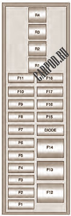
Block #1
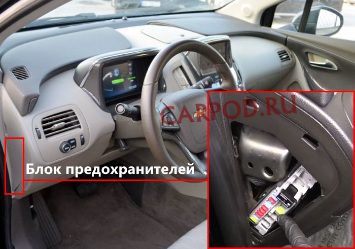
The main unit is located on the driver’s side at the end of the dashboard. To access it, you need to remove the protective trim.
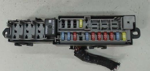
Photo – example of execution.
| No. | Description | Current, A |
| F1 | Power socket (cigarette lighter fuse chevrolet volt) | 20 |
| F2 | Radio | 15 |
| F3 | Instrument cluster (left-hand drive) / Hands-free telephone (right-hand drive) | 10 |
| F4 | Infotainment display | 10 |
| F5 | Heating, ventilation and air conditioning / Integrated switches in the center console | 10 |
| F6 | Airbag (diagnostic module) | 10 |
| F7 | Data Link Connector, Left (Primary Left Drive), Data Link Connector, Left (Secondary Right Drive) | 15 |
| F8 | Ignition Lock (Left Hand Drive) | |
| F9 | GSM (OnStar only) | 10 |
| F10 | Body control module / Keyless entry system / Power control / Center brake light / License plate lights / Left daytime running light / Left side light / Rear lid release relay control / Washer pump relay control / Switch indicator lights | 15 |
| F11 | Body Control Unit 4 / Left Headlight | 15 |
| F12 | Fan (right hand drive) | |
| F13 | Empty | – |
| F14 | Empty | – |
| F15 | X80H Auxiliary Power Socket – Center Console | 20 |
| F16 | Empty | – |
| F17 | Empty | – |
| F18 | Empty | |
| No. | Relay modules | |
| R1 | Additional power relay for sockets | |
| R2 | Empty | |
| R3 | Empty | |
| R4 | Door lock (if available with left-hand drive), child lock (with right-hand drive) | |
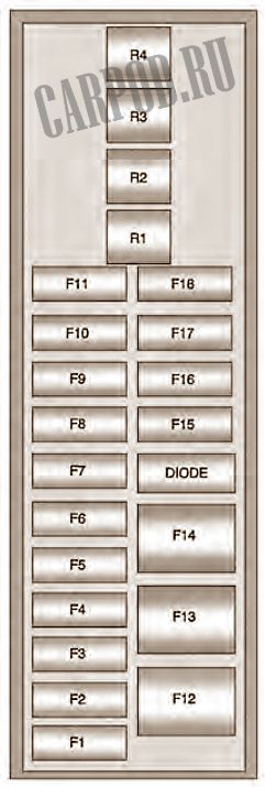
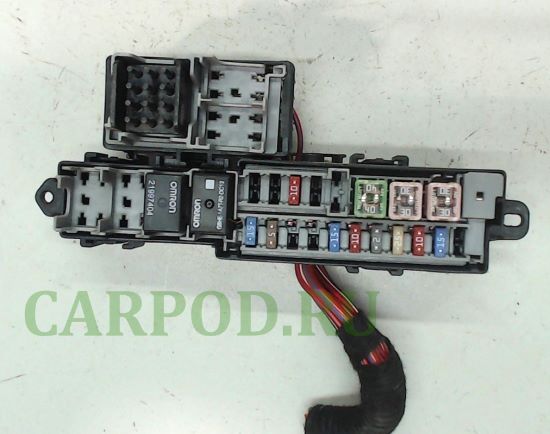
Block #2
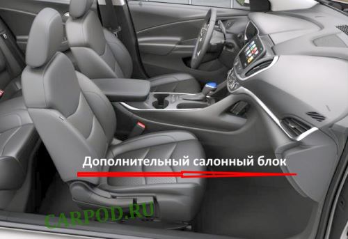
An additional mounting block is located at the end of the instrument panel on the passenger side.
| No. | Transcript | Current, A |
| F1 | Steering wheel switches / Lighting | 2 |
| F2 | Ignition Switch (Right Hand Drive) | 10 |
| F3 | Instrument cluster (Right hand drive) / Hands-free telephone (Left hand drive) | |
| F4 | Body Equipment Control Unit / Right Headlight | 15 |
| F5 | Body control module / Tailgate light / Right daytime running light / Gear selector lock / Rear light switch / Rear fog light | 15 |
| F6 | Accessory Power Relay / Front Right Turn Signal / Rear Left Brake & Turn Signal Lamp / Right Parking Lamp / Remote PRNDL | 15 |
| F7 | Body control unit 6 / Lighting / Backlight / Reversing light | 15/7.5 |
| F8 | Body Control Module 7 / Front Left Turn Signal / Rear Right Stop and Turn Signal Lamp / Child Lock Relay Control | 15 |
| F9 | Body Equipment Control Unit 8 / Locks | 20 |
| F10 | Data Link Connector, Right (Secondary Left Drive), Data Link Connector, Right (Primary Right Drive) | 10/15 |
| F11 | Tilt sensor (if available) | 7.5 |
| F12 | Fan Motor (Left Hand Drive) | 30 |
| F13 | Empty | – |
| F14 | Empty | – |
| F15 | Empty | – |
| F16 | Empty | – |
| F17 | Empty | – |
| No. | Relay | |
| R1 | Empty | |
| R2 | Empty | |
| R3 | Empty | |
| R4 | Door lock (if available with right-hand drive), child lock (with left-hand drive) | |
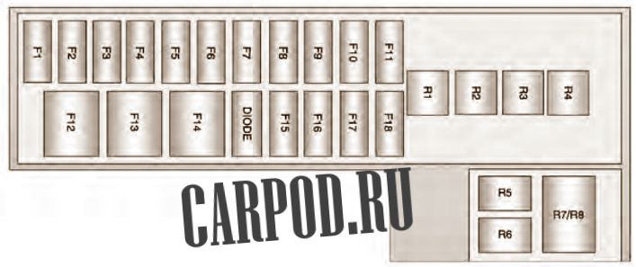
In the trunk
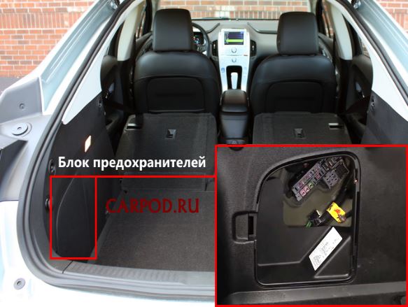
Located on the left side of the trunk, behind the trim.
General view.
| No. | Description | Current, A |
| F1 | Empty | – |
| F2 | Fuel System Control Module | 15 |
| F3 | Passive Start/Passive Entry (PEPS) | 10 |
| F4 | Heated seats ( if equipped ) | 25 |
| F5 | Driver Door Switches (Outside Rear View Mirror/Charge Port Door Open/Refuel Request/Driver Window Switch) | 20/2 |
| F6 | Fuel (daily valve and evaporator leak test module) | 10 |
| F7 | Additional power supply Cooling fan | 15 |
| F8 | Amplifier ( if available ) | 2 |
| F9 | Digital audio broadcasting ( if available ) | 10 |
| F10 | Adjustable voltage / Ultrasonic parking assistance system front and rear ( if equipped ) | 5 |
| F11 | Beep | 15 |
| F12 | Rear electric windows | 30 |
| F13 | Electric parking brake | 30 |
| F14 | Rear window defroster | 40 |
| F15 | Empty | – |
| F16 | Opening the trunk door | 10 |
| F17 | Empty | – |
| F18 | Empty | – |
| No. | Purpose of the relay | |
| R1 | Rear window heating | 40 |
| R2 | Tailgate Opening / Tailgate Lock Release Relay | 20 |
| R3 | Empty | |
| R4 | Empty | |
| R5 | Empty | |
| R6 | Empty | |
| R7 | Beep | |
| R8 | ||