Mazda 2 DY (2nd generation) was produced in 2003, 2004, 2005, 2006 and 2007. In this article you will find information describing the location of all electronic control units, we will describe in detail the fuses and relays of the Mazda 2 DY with their diagrams. We will highlight the fuse responsible for the cigarette lighter.
The number of block elements may vary. Check with your diagrams on the back of the cover.
Location of control units
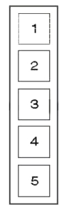
General block layout diagram

Description
| 1 | Air conditioning control unit (in the heater control panel) |
| 2 | Air conditioner/heater fan motor relay – behind the dashboard |
| 3 | Heater/Air Conditioner Fan Motor Resistor – Passenger Footwell |
| 4 | Impact sensor (SRS), front |
| 5 | Anti-theft system control unit behind the dashboard |
| 6 | Anti-theft alarm sound |
| 7 | Rechargeable battery |
| 8 | Central locking control unit |
| 9 | Clutch drive control unit – engine compartment |
| 10 | Diagnostic Connector (DLC) |
| 11 | Power window control unit (in the driver’s door switch) |
| 12 | Cooling system fan motor resistor – radiator shroud |
| 13 | Fog light relay |
| 14 | Fuse/relay block, engine compartment |
| 15 | Fuse/relay block instrument panel 1 |
| 16 | Fuse/relay block instrument panel 2 |
| 17 | Fuse/relay block instrument panel 3 |
| 18 | Headlight leveling motor, left |
| 19 | Headlight leveling motor, right |
| 20 | Rear window heater relay |
| 21 | Sound signal |
| 22 | Immobilizer ring antenna – near the ignition switch |
| 23 | Turn signal relay-interrupter |
| 24 | Instrument cluster control unit (in the instrument panel) |
| 25 | Rear fog light relay |
| 26 | Rear window washer pump – integrated into the windshield washer pump |
| 27 | Relay block includes: Windshield wiper motor relay, windshield washer pump relay, rear window wiper/washer relay, horn relay, front/rear clearance relay |
| 28 | Side impact sensor, front left – lower part of the center pillar |
| 29 | Side impact sensor, front right-lower part of the B-pillar |
| 30 | Starter relay |
| 31 | SRS electronic control unit |
| 32 | Electronic gearbox control unit – in the electronic clutch control unit |
| 33 | Gearbox shift drive – on the gearbox |
| 34 | Gear shift control unit – automatic transmission selector |
| 35 | Vehicle speed sensor, with ABS system – ABS electronic control unit |
| 36 | Vehicle speed sensor, without ABS system – on the gearbox |
| 37 | Low windshield washer fluid level sensor |
| 38 | Windshield washer pump motor |
| 39 | Windshield wiper intermittent relay – in the switch box |
Blocks in the cabin
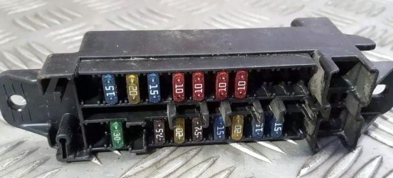
Main fuse block
Located at the bottom of the instrument panel behind a protective cover.
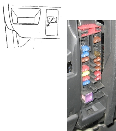
Example of markings from the unit cover

Scheme
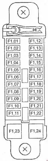
Marking
| F01 | Not used |
| F02 | Not used |
| F03 | 15A Interior lighting |
| F04 | 15A Cigarette lighter |
| F05 | 7.5A Electric side rearview mirrors |
| F06 | Not used |
| F07 | 10A Instrument cluster |
| F08 | 20A Wipers and washers |
| F09 | 10A Active safety system |
| F10 | 15A Engine management system |
| F11 | 15A Gearbox control unit |
| F12 | 30A Electric window regulator |
| F13 | Not used |
| F14 | Not used |
| F15 | Not used |
| F16 | 7.5A Starter |
| F17 | 7.5A Reversing lights |
| F18 | 7.5A Instrument cluster lighting |
| F19 | 7.5A Air conditioner compressor electromagnetic clutch |
| F20 | 7.5A Air conditioner |
| F21 | 10A Rear door window wiper and washer |
| F22 | 10A Rear door glass heater |
| F23 | Not used |
| F24 | Not used |
Fuse number 4 at 15A is responsible for the cigarette lighter.
Additional fuse block
It is installed behind the glove compartment on the passenger side.
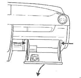
Photo – example
Scheme
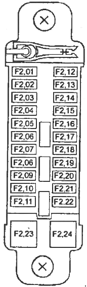
Appointment
| F01 | Not used |
| F02 | 30А ABS |
| F03 | Not used |
| F04 | 7.5A Generator |
| F05 | 20A Fuel pump |
| F06 | 7.5A Electronic engine and transmission control unit |
| F07 | 15A Air flow sensor, engine management system |
| F08 | 20A Air flow sensor, engine management system |
| F09 | 15A Stop signals |
| F10 | 15A Emergency alarm |
| F11 | Not used |
| F12 | Not used |
| F13 | Not used |
| F14 | 15А TNS |
| F15 | 20А ABS |
| F16 | 15A Heated side rear view mirrors |
| F17 | 10A High beam (right headlight) |
| F18 | 10A High beam (left headlight) |
| F19 | 10A Low beam (right headlight) |
| F20 | 10A Low beam (left headlight) |
| F21 | Not used |
| F22 | Not used |
| F23 | Not used |
| F24 | Not used |
Relay block
Scheme
Transcript
- Headlight low beam relay
- Headlight high beam relay
- Fuel pump relay
- Anti-theft alarm relay
- Engine control system relay
Block under the hood
Located next to the battery.
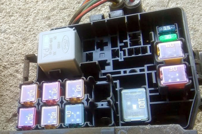
Scheme
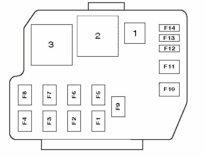
Description
| 1 | Throttle position relay (air conditioning system) |
| 2 | Cooling system fan motor relay (high speed) |
| 3 | Cooling system fan motor relay |
| F1 | 50A Glow plugs (Diesel), auxiliary heater |
| F2 | 40A Air conditioner/heater fan motor |
| F3 | 50A Ignition switch |
| F4 | 50A Cooling system fan motor |
| F5 | 60A Automatic clutch drive control |
| F6 | 60A Ignition switch |
| F7 | 30A Headlights |
| F8 | 60A Engine control |
| F9 | 100A Battery Power Distribution |
| F10 | 30A Rear window heater |
| F11 | 60A Anti-lock braking system (ABS) |
| F12 | 20A Electric window regulator |
| F13 | 30A Central locking |
| F14 | 15A Fog lights |