Toyota Altezza 1 generation was produced in 1998, 1999, 2000, 2001, 2002, 2003, 2004, 2005 with body marking E10. In some countries it is also known as Lexus IS 200. In this article we will show the description of fuses and relays Toyota Alteza (Lexus IS200) with block diagrams and photo examples of their implementation. Let’s highlight the cigarette lighter fuse.
Blocks in the cabin
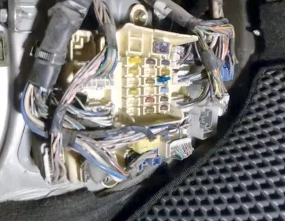
Block on the left side
On the left side, under the panel, behind the side protection, is the fuse and relay box.
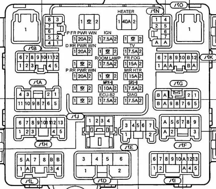
| P FR P/W | 20A Electric window lifter front passenger door |
| IGN | 7.5A Electronic Engine Control Unit |
| DOOR DL | — |
| D RR P/W | 20A Electric window lifter rear right door |
| TV | 7.5A Multi-functional display |
| DOME | 7.5A Interior Lighting, Clock |
| FR FOG | 15A Front fog lights |
| P RR P/W | 20A Electric window lifter rear left door |
| MIR HTR | 15A Mirror heater |
| MPX-B | 10A Instrument cluster, main control unit, air conditioning control unit |
| SRS-B | 7.5A Airbags |
| ECU-B2 | 7.5A Rear Fog Lights |
| OBD | 7.5A OBD connector |
Relay diagram from the back of the unit
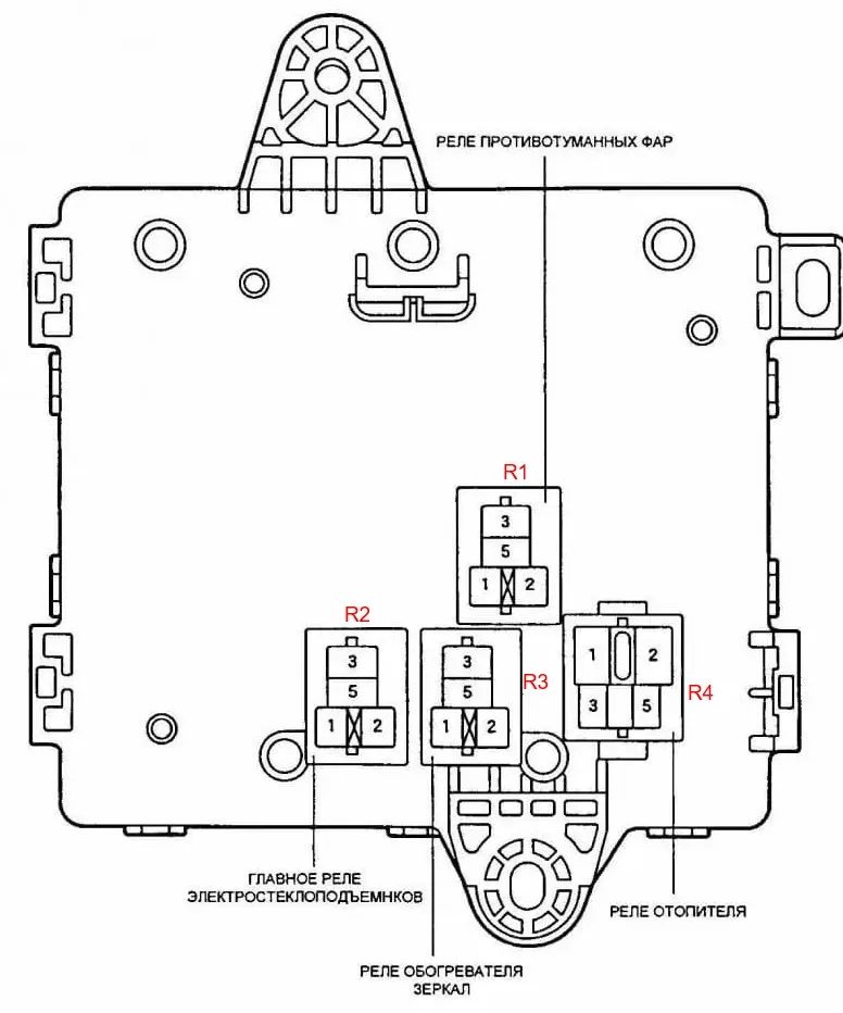
- R1 – Fog light relay
- R2 – Main relay for electric lifts
- R3 – Mirror heater relay
- R4 – Heater relay
Block on the right side
On the right side, under the panel, behind the side protection, there is another fuse and relay box.
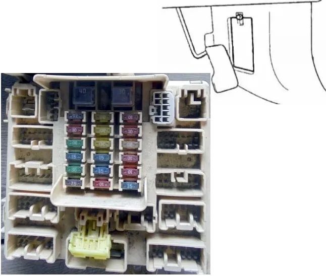
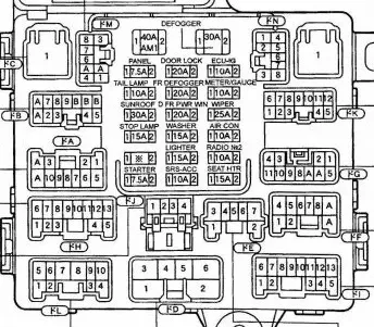
| PANEL | 7.5A Switch and control panel illumination, air conditioning and heating control panel illumination, radio illumination |
| DOOR | 20A Central locking |
| ECU-IG | 10A ABS, TRC, Main Control Unit, Air Conditioning Control Unit |
| TAIL | 10A Front and rear side lights, number plate light |
| FRDEF | 20A Windshield Wiper Blade De-icer |
| GAUGE | 10A Instrument cluster, rear fog lights |
| S/ROOF | 30A Hatch |
| D FRP/W | 20A Driver’s door electric window lifter |
| WIPER | 25A Windscreen Wiper Motor |
| STOP | 15A Brake lights |
| WASHER | 15A Washer Switch |
| A/C | 10A Air Conditioner |
| DP/SEAT | 30A Electric Seat Drive |
| PWR OUTLET | 15A Socket |
| CIG | 15A Cigarette Lighter |
| RADIO №2 | 10A Radio, Multi-function Display |
| STARTER | 7.5A Starter |
| SRS-ACC | 10A Airbags |
| SEAT HTR | 15A Heated Seats |
The operation of the cigarette lighter is controlled by a fuse marked as CIG for 15A.
Relay diagram from the back of the unit
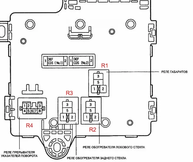
- R1 – Side light relay
- R2 – Main windshield heater
- R3 – Rear window heater main
- R4 – Direction indicator relay
Blocks under the hood
Location
Layout of blocks under the hood
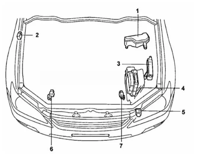
- fuse and relay box and relay box #2
- remote lock buzzer
- Relay block #3 in the engine compartment
- Electronic Engine Control Unit
- headlight washer relay
- Front SRS sensor (right)
- Front SRS sensor (left)
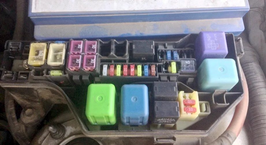
Fuse and relay box
It is installed next to the battery.
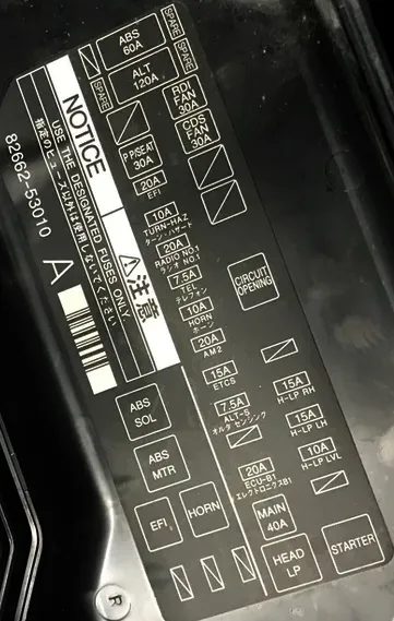
| 120 A ALT – charging system, electric windows, mirror heaters, glass heaters, headlights, side lights, fog lights, lighting |
| 40A MAIN – starting system, headlights, fog lights |
| 20A EFI – electronic control unit for engine and automatic transmission |
| 10A TURN& HAZARD – direction indicators, hazard warning lights |
| 10A HORN – sound signal |
| 7.5A ALT-S – charging system |
| 20A RADIO No. 1 – audio system, navigation system |
| 15A ETCS – electronic control unit for engine and automatic transmission |
| 30A RDI FAN – cooling system fan |
| 30A CDS FAN – cooling system fan |
| 30A CDS 2 – cooling system fan |
| 60A ABS – ABS, TRC |
| 7.5A ABS2 – ABS |
| 25A EFI – electronic control unit for engine and automatic transmission |
| 20A AM2 – starting system |
| 30A P PWR SEAT – electric seat drive |
| 30A H-LP CLN – headlight cleaners |
| 15A H-LP RH – right headlight |
| 15A H-LP LH – left headlights |
| 15A H-LP R LWR – right headlights |
| 15A H-LP L LWR – headlights left |
| 10A H-LP R UPR – right headlights |
| 10A H-LP L UPR – headlights left |
Relay block 3
Scheme
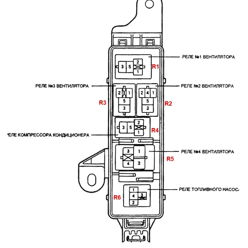
- R1 – Fan relay 1
- R2 – Fan relay 2
- R3 – Fan relay 3
- R4 – Air conditioning compressor relay
- R5 – Fan relay 4
- R6 – Fuel pump relay