Mitsubishi Pajero 3rd generation was produced in 1999, 2000, 2001, 2002, 2003, 2004, 2005 and 2006. During this time, the model has undergone restyling. In some countries it is known as Mitsubishi Montero 3. In our material we will show the general location of electronic control units, describe in detail the fuses and relays of Mitsubishi Pajero 3 with block diagrams and photo examples of execution. We will highlight the fuse responsible for the cigarette lighter.

There may be differences between the material presented and your Mitsubishi Pajero (Montero) 3, depending on the region of delivery and the level of equipment. Check the designation with your diagrams on the back of the protective cover.
Block arrangement
General layout of control units
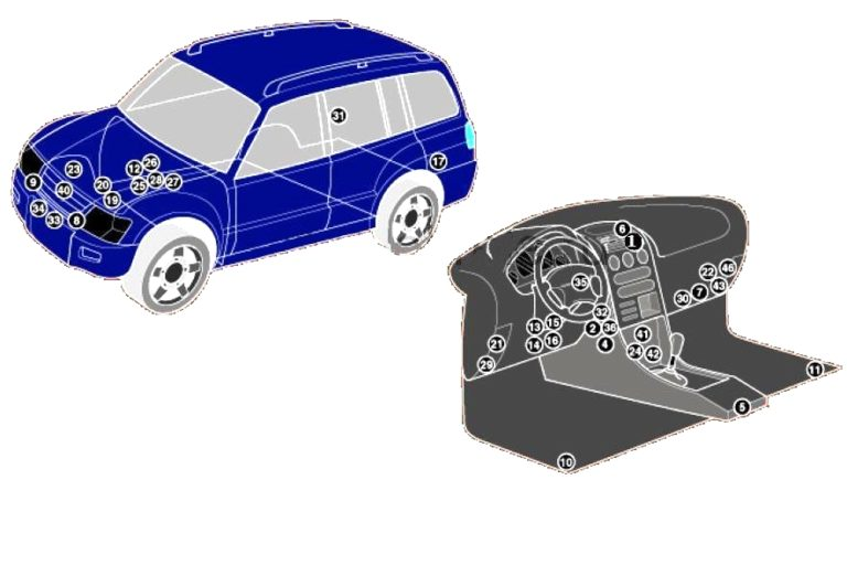
Marking
| 1 | Air temperature sensor supplied from the instrument panel ventilation grille |
| 2 | Intake air temperature sensor (air conditioner/heater) |
| 4 | Air conditioner/heater fan motor control unit (manual temperature control) |
| 5 | Air conditioner/heater fan control unit – rear |
| 6 | Sunlight sensor (air conditioning system) |
| 7 | Antenna block |
| 8 | Impact sensor (airbag), left front |
| 9 | Impact sensor (airbag), right front |
| 10 | Side impact sensor, driver’s side – under the front seat |
| 11 | Side impact sensor, passenger side – under the front seat |
| 12 | Rechargeable battery |
| 13 | Diagnostic Connector (DLC) 1 – 2.5D (4D56) (2002^) |
| 14 | Diagnostic Connector (DLC) 1 – 3.5 (6G74) /3.2D (4M41) |
| 15 | Diagnostic Connector (DLC) 2 – 2.5D (4D56) (2002^) |
| 16 | Diagnostic Connector (DLC) 2 – 3.5 (6G74) /3.2D (4M41) |
| 17 | Differential lock control unit – rear |
| 19 | Coolant heater relay 1 |
| 20 | Engine oil level sensor relay |
| 21 | Engine oil level sensor |
| 22 | 4WD electronic control unit |
| 23 | Fuse/relay block, engine compartment 1 |
| 24 | Fuse/relay block, engine compartment 2 |
| 25 | Fuse/relay block, engine compartment 3 |
| 26 | Fuse/relay block, engine compartment 4 |
| 27 | Fuse/relay block instrument panel |
| 28 | Heater fan motor resistor |
| 29 | Heater outlet temperature sensor |
| 30 | Heater radiator temperature sensor |
| 31 | Horn 1 – behind the front bumper |
| 32 | Horn 2 – behind the front bumper |
| 33 | Electronic immobilizer control unit |
| 34 | Immobilizer control unit – 2.5D (4D56T) |
| 40 | Transfer case control unit |
| 41 | Electronic gearbox control unit |
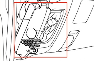
Cabin block
Located under the driver’s dashboard.
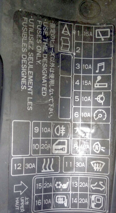
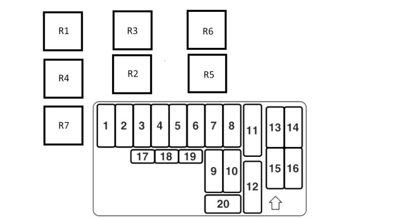
Fuse description
| 1 | 15A Rear window wiper glass |
| 2 | Reserve |
| 3 | 10A Radio, Audio |
| 4 | 15A Cigarette lighter |
| 5 | 10A Air conditioning system, ABS system, emergency braking system, fuel filter heater, windshield heater, multifunction control unit 1, transfer case control unit |
| 6 | 10A Cruise control system, exhaust gas recirculation (EGR) system, instrument cluster, immobilizer 2^ (4D56T), differential lock control unit, 4WD electronic control unit, SRS system, throttle control solenoid valve, vehicle speed sensor |
| 7 | 20A Engine control |
| 8 | 10A Reversing lights |
| 9 | 10A Rear fog light |
| 10 | 20A Central locking |
| 11 | 30A Rear window heater |
| 12 | 30A Heater |
| 13 | 20A Roof hatch |
| 14 | 10A ABS |
| 15 | 20A Heated seats |
| 16 | 10A Heated mirrors |
| 17 | Reserve |
| 18 | Reserve |
| 19 | Reserve |
| 20 | Reserve |
Fuse number 4 at 15A is responsible for the cigarette lighter. There is also a fuse in the block under the hood responsible for the cigarette lighter.
Relay decoding
- Rear fog light relay
- Electric window lifter relay
- Generator relay
- Heater fan motor relay – rear air conditioning
- Rear window heater relay
- Heater fan motor relay – front air conditioning
- Auxiliary ignition circuit relay
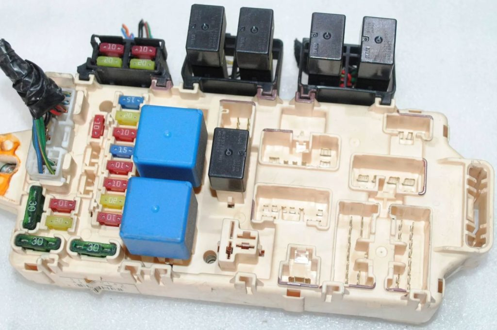
Blocks under the hood
Main unit
The main unit with fuses and relays is located next to the battery.
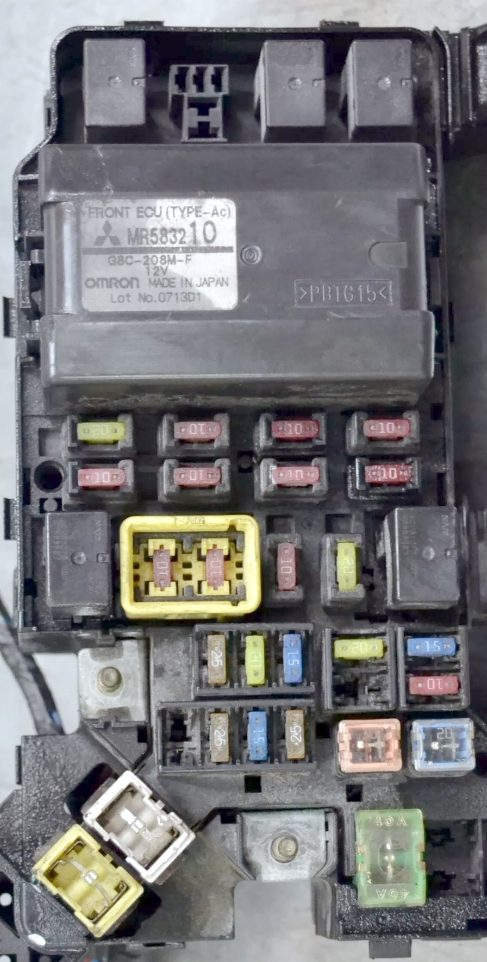
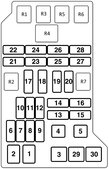
Appointment
| R1 | A/C Condenser Fan Motor Relay – High Speed |
| R2 | Horn relay |
| R3 | A/C condenser fan motor relay – low speed |
| R4 | Multifunctional control unit 1 |
| R5 | Windshield Defroster Relay – Windshield Wipers |
| R6 | Air conditioner compressor electromagnetic clutch relay |
| R7 | Reserve |
| 1 | 120A Fuse/relay block 1 in engine compartment, fog lights, headlights, tail lights (2001), multifunction control unit 1 (2002^) |
| 2 | 60A Fuse/Relay Block, Engine Compartment 1 |
| 3 | 40A Ignition switch |
| 4 | 40A Electric seats, electric window lifters |
| 5 | 20A Engine control |
| 6 | 20A Engine control |
| 7 | – |
| 8 | 15A Additional equipment |
| 9 | 25A Fuel filter heater |
| 10 | 25A Air conditioner |
| 11 | 20A Air conditioner |
| 12 | 15A Windshield Defroster Relay – Windshield Wipers |
| 13 | – |
| 14 | 20A Automatic transmission |
| 15 | 10A Generator, central locking, turn signals/emergency alarm |
| 16 | 15A Anti-lock braking system (ABS), brake lights |
| 17 | 10A Audio system, cigarette lighter , clock |
| 18 | 10A Air conditioning system, audio system, central locking, clock, ESP electronic control unit, interior lights, multifunction control unit 1, transfer case control unit |
| 19 | 10A Air conditioner |
| 20 | 20A Fog lights |
| 21 | 10A Audible signal |
| 22 | 20A Windshield wiper/washer |
| 23 | 10A Engine management system, rear (right) |
| 24 | 10A Rear left side marker lamp |
| 25 | 10A Low beam bulb (left) |
| 26 | 10A Low beam bulb (right) |
| 27 | 10A High beam bulb (left) |
| 28 | 10A High beam lamp (right) |
| 29 | Reserve |
| 30 | 40A Coolant heater |
Fuse number 17 at 10A is responsible for the additional cigarette lighter sockets.
Relay block
Scheme
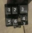
Description
- Fuel pump relay that pumps
- Injector relay
- System relay (emergency braking)
- Reserve
- Engine control system relay
- Throttle control unit relay
- Reserve
Individual fuses and relays can be installed outside these units, for example, a relay for the pump motor or the ABS emergency braking system. Also, high-power fuses can be installed on the positive terminal of the battery: 40/60A – ABS and 80A – Glow plugs.