Mercedes-Benz Sprinter 3rd generation with body markings 907 and 910 was produced in 2018, 2019, 2020, 2021, 2022, 2023. In this material you can find a description of fuses and relays Mercedes Sprinter 907 910 with block diagrams and photo examples of their location. Let’s highlight the cigarette lighter fuse.

The design of the blocks and the purpose of their elements may differ from those presented and depend on the year of manufacture, equipment level and delivery region of your vehicle.
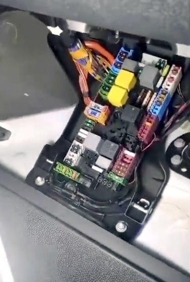
Fuse and relay block under the panel
Under the dashboard, in the front passenger’s footwell, is a main unit with fuses and relays.

Description
Fuses
| MF1 | |
| 15-1 | 5A Engine control unit; |
| Common Powertrain Module (CPC); | |
| ESP module; | |
| all-wheel drive module; | |
| Retarder; | |
| Air suspension. | |
| MF2 | |
| 15-2 | 5A Feedback cable, relay terminal 15; |
| Headlight angle adjustment; halogen headlight; | |
| Tachograph TShV; | |
| Active brake booster radar sensor; | |
| reversing alarm switch-off, power take-off box, operating speed adjustment; | |
| Connection to DIN socket. | |
| MF3 | |
| 30-T | 7.5A Multifunctional camera; |
| Tachograph TShV; | |
| Connection to DIN socket, roof; | |
| Terminal 15, undervoltage relay; | |
| Instrument panel; | |
| Central oil pump. | |
| S9 | |
| 1 | Not assigned |
| 2 | 10A Common Transmission Module (CPC) |
| 3 | 10A Engine control unit OM642/OM651/M274 |
| 4 | 7.5A DIN connector, cabin |
| 5 | 10A Common Transmission Module (CPC) |
| 6 | 5A Radiator fan (not for OM654) |
| S10 | |
| 7 | 30A Automatic transmission |
| 8 | 30A Body Controller |
| 9 | 30A Body Controller |
| 10 | 30A Heating, SCR catalyst. |
| 11 | 10A Ceiling control module (standard); |
| 10A Ceiling control module, cab chassis; | |
| 15A Ceiling control module, high. | |
| 12 | 15A Pump, SCR catalyst |
| S11 | |
| 13 | 60A Automatic transmission NAT3 |
| S12 | |
| 14 | 25/40A ESP valves (Premium), cars with electromechanical parking brake; |
| ESP valves (Standard). | |
| S13 | |
| 16 | 60A ESP pump |
| S14 | |
| 17 | 30A Controller |
| 18 | 30A Body Controller |
| 19 | 10A Bodybuilder electrical connection terminal block |
| 20 | 25A Front passenger door control unit |
| 21 | 25A Driver’s door controller |
| 22 | 10A Air suspension control unit (LFA) |
| S15 | |
| 23 | 25A Fan control unit |
| 24 | 7.5A USB socket (cockpit, glove box); |
| Converter socket 115/230 V. | |
| 25 | 15A Cigarette lighter, center console |
| 26 | 15A Dashboard Socket |
| 27 | 25A Converter socket, 115V/230V. |
| 28 | 7.5A Pre-installation of the radio; |
| Freight elevator; | |
| Voltage converter antenna; | |
| Converter socket, 115V/230V for vehicles with external battery. | |
| S16 | |
| 30-1 | Not assigned |
| 30-2 | Not assigned |
| 30-3 | 5A Central locking |
| 30-4 | 5A Alarm (ATA) |
| 30-5 | Not assigned |
| 30-6 | 10A Electronic ignition lock control unit |
| 31 | 25A Start, relay contact 15-II |
| S17 | |
| 32 | Not assigned |
| S18 | |
| 33 | 5A Voltage quality sensor (SEB) |
| S19 | |
| 34 | 10A Electronics for interior lighting |
| S1 | |
| 35 | 7.5A Advance Caravanning (ACU) – motorhome |
| S2 | |
| 36 | 5A Air conditioner control panel |
| 37 | 5A Electric Steering Lock (ESTL) |
| 38 | 10A Steering column (SCSM) |
| 39 | 10A Antenna; |
| Navigation; | |
| Two-way radio. | |
| 40 | 5A Flashing beacon |
| 41 | 25A Radio multimedia system (C5/NTG6), radio pre-installation |
| S3 | |
| 42 | Not assigned |
| S4 | |
| 43 | Not assigned |
| S5 | |
| 44 | 5A Multimedia system control panel |
| 45 | 5A Charger bracket; |
| Wireless Mobile Interface (WMI). | |
| 46 | 7.5A Multimedia Interface (MMI) |
| 47 | 5A Hermes (UMTS/LTE connection module) |
| 48 | 5A Stationary heating Telestar |
| 49 | 5A Central display |
| S6 | |
| 50 | 5A Additional left headlight (platform body manufacturer) |
| 51 | 5A Additional right headlight (platform body manufacturer) |
| 52 | 7.5A Airbag control unit |
| 53 | 5A Diagnostics |
| 54 | 5A Relay Power Supply |
| 55 | 7.5A TS Engine (Diesel), Engine Control Unit (OM651) |
| S7 | |
| 57 | 10A Soot particle sensor; |
| NOx sensor; | |
| Soot particle sensor (not for OM654) | |
| 58 | 10A Engine, exhaust gas recirculation (EGR) (OM642/OM651); |
| Engine (not for OM654) | |
| 59 | 15A NOx sensor before and after the catalyst (not OM654) |
| 60 | 10A Lambda probe |
| 61 | 7.5A Engine M274; Engine (OM642/OM651). |
| H2 | |
| 62 | 15A Engine control unit (not for OM654) |
| 63 | 20/25A Engine control unit; Engine (M274); |
| Engine (not for OM654) | |
| S8 | |
| 64 | 30A Body Controller |
| 65 | 30A Body Controller |
| 66 | 15A Roof fan |
| 67 | 25A Fuel Metering Control Module (FSCM) |
| 68 | 15A Right LED headlight |
| 69 | 15A Left LED headlight |
| H2 | |
| 70 | 30A Janitors |
Relay
| R1 | 30A Reserve |
| R2 | 50A Terminal 87, engine |
| R3 | 30A Terminal 87, Common Drive Module (CPC) |
| R4 | 40A Terminal 15-1 |
| R5 | 40A Turns the wipers on and off. |
| R6 | 40A Reserve |
| R7 | 40A Wiper speed |
| R8 | 40A Terminal 50, starter |
| R9 | 50A Terminal 15R (vehicles without additional battery) |
| R10 | 30A Terminal 15-2 |
| R11 | 50A Terminal 15R (vehicles without additional battery) |
Fuses with numbers 24, 25, 26, 27, as well as additional elements in the driver’s seat unit, are responsible for the operation of the USB port and cigarette lighter.
Fuse and relay blocks under the driver’s seat
Fuse and relay blocks can be installed under the driver’s seat, as well as the passenger seat.

Fuse block
To access the unit, you must remove the protective cover on the driver’s seat side.


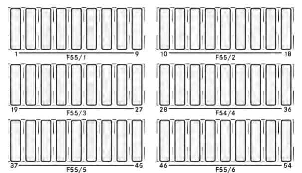
Marking
| F55/1 | |
| 1 | 10A Additional turn signal lamp |
| 2 | 15A Rear window wiper, right |
| 3 | 30A All-wheel drive |
| 4 | 25A Terminal block for electrical connection |
| 5 | 25A Driver’s seat adjustment unit |
| 6 | 10A Driver’s seat heating unit |
| 7 | 25A Driver’s lumbar support |
| 8 | 5A Tire pressure monitoring |
| 9 | 5A Parking assistant;Main camera (RVC). |
| F55/2 | |
| 10 | 25A Right trailer coupling (trailer socket) |
| 11 | 15A Control unit with trailer socket |
| 12 | 25A Left towbar (trailer socket) |
| 13 | 15A Control unit with trailer socket |
| 14 | 25A Multi-function Module (MPM) |
| 15 | 25A Multi-function Module (MPM) |
| 16 | 25A Rear chamber blower |
| 17 | 20A Additional heating (water heating) |
| 18 | 15A Automatic transmission, additional oil pump |
| F55/3 | |
| 19 | 15A Parking heater; |
| Terminal 15 on the auxiliary battery. | |
| 20 | 5A Auxiliary Battery Voltage Measurement |
| 21 | 15A Rear window heater, left |
| 22 | 15A Right rear window heating |
| 23 | 7.5A Lift truck / dump truck (before installation) |
| 24 | 15A Terminal block for electrical connection |
| 25 | 5A Dahu Fan Relay |
| 26 | 7.5A Special signal, cab body manufacturer |
| 27 | 30A Heated rear window |
| F55/4 | |
| 28 | 15/30A Sliding door on the left; |
| Electric sliding door on the left. | |
| 29 | 15/30A Sliding door right; |
| Electric sliding door on the right. | |
| 30 | 5A Antenna Switch Unit |
| 31 | 7.5A Automatic transmission |
| 32 | 10A Automatic transmission |
| 33 | 30A Brake booster |
| 34 | 15/30A Siren relay; Motorhome preparation. |
| 35 | 15/30A Strobe light with siren; |
| 30A Preparing for a motorhome. | |
| 36 | 30A Preparing for a motorhome |
| F55/5 | |
| 37 | 10A Electric step left |
| 38 | 10A Electric footrest right |
| 39 | 5A Safety buzzer; |
| Electric step, right and left. | |
| 40 | 10A Automatic transmission (NAT2) |
| 41 | 5A Terminal 15, special signal |
| 42 | 5A Rear View Camera (RVC); |
| Interior mirror with rear view monitor. | |
| 4 3 | 15A Power socket, cabin |
| 44 | 15A Power outlet, D-pillar, left |
| 45 | 15A Power socket, D-pillar, right |
| F55/6 | |
| 51 | 5/7.5A USB port, left |
| 52 | 5/7.5A USB port, right |
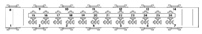
Relay block
It is installed under the driver’s seat itself.
Scheme
Appointment
| 1 | Heated windshield |
| 2 | Terminal 15 |
| 3 | Heated rear window |
| 4 | Sockets, rear |
| 5 | Interior lighting |
| 6 | Not used |
| 7 | Not used |
| 8 | Not used |
| 9 | Not used |
| 10 | Not used |
| 11 | Not used |
| 12 | Not used |
| 13 | Not used |
| 14 | Not used |
| – | Mini relay |
| 15 | Right rear wiper |
| 16 | Manufacturer’s terminal block housing |
| 17 | Switch, reverse warning light |
| 18 | Roof fan |
| 19 | Additional oil pump |
| 20 | Electric footrest right 1 |
| 21 | Electric footrest right 2 |
| 22 | Electric step left 1 |
| 23 | Electric step left 2 |
| 24 | siren |
| 25 | Flashing beacon with siren |
| 26 | Loading elevator |
Battery fuse block
A block of power fuses, made in the form of a fuse insert, is installed on the positive terminal of the battery.
Scheme

Transcript
| F150/1 (MFB-1) | |
| 1 | Battery sensor |
| 2 | Not assigned |
| 3 | Main fuse block (MFB-2) |
| 4 | 50A Power Distribution Center, Terminal 30 (F30-1 – F30-6) |
| 5 | 125A PTC Auxiliary Heater |
| F150/4 (MFB-2) | |
| 1 | 125A Terminal 30T, fuse block, driver’s seat base (F55/1-F55/6) |
| 2 | 125A Electrical control |
| 3 | 300A Generator |
| 4 | 400A Generator |
| 5 | 175A Power Distribution Center (PDC), FB-P |
| 6 | 80A Glow output stage (GZE) |
| 7 | 40/70/80A Radiator fan (not for OM654); |
| Engine radiator fan; | |
| Radiator fan (not for OM654). | |
| 8 | 100A Motorhome Main Fuses |
| 9 | Not assigned |
| 10 | 25/50/100A Rear air conditioning |
| 11 | 100/150A Auxiliary battery/battery disconnect relay; |
| Retarder without additional battery. | |
| 12 | 40A Air suspension (LFA) |
| 13 | 80A Heated windshield |
| F150/5 (MFB-ZB) | |
| 1 | 100A Retarder |
| 2 | 250A Lift truck / dump truck (preparation) |
| 3 | Additional battery |
| 4 | 150A Battery Disconnect Relay |
| 5 | 60A Socket, Converter |
| 6 | 25A Additional heating |
| F59/1 and F59/2 | |
| 1 | 40A Heated windshield |
| 2 | 40A Heated windshield right |