The Hyundai Creta mini crossover was introduced in 2014. It was sold in 2015, 2016, 2017, 2018, 2019, 2020, 2021 and to the present. During this time, the model has undergone an update. It is supplied worldwide. In other countries, it is also known as the H yundai ix25 and Hyundai Cantus. In this publication, you will find a description of the fuses and relays of the Hyundai Creta with block diagrams and their locations. We note the fuse responsible for the cigarette lighter.

Depending on the trim level and year of manufacture of your Hyundai Creta, different versions of the blocks and the purpose of the elements in them are possible. Compare the information with your diagrams.
Cabin block
Located under the dashboard on the driver’s side behind a protective cover.
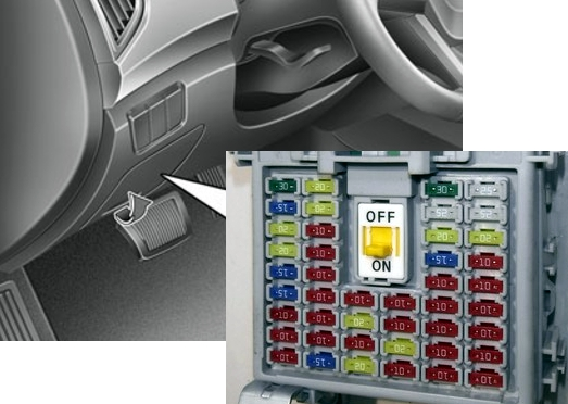
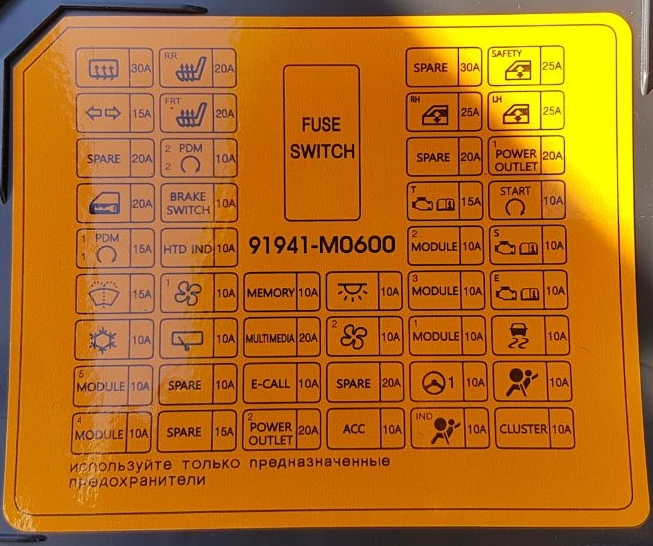
Example of a circuit from the block cover
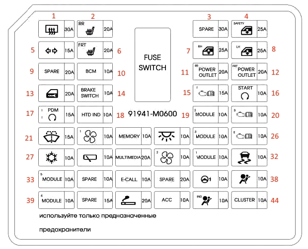
Description
| 1 | 30A rear window heating relay |
| 2 | 20A rear seat heater control module |
| 3 | 30A reserve |
| 4 | 25A driver’s power window module with pinch protection |
| 5 | 15A turn signal and hazard warning light |
| 6 | 20A driver/passenger seat heater control module |
| 7 | 25A right electric window lifter |
| 8 | 25A left electric window lifter |
| 9 | 20A reserve |
| 10 | 10A electronic key control unit, immobilizer module |
| 11 | 20A rear power socket |
| 12 | 20A front power socket (cigarette lighter) |
| 13 | 20A lock/unlock relay, trunk door unlock relay |
| 14 | 10A electronic key control unit, brake light switch |
| 15 | 15A manual transmission range switch, manual transmission unit (fuse – f26 (reversing lights)) |
| 16 | 10A PP block (security alarm relay), gearbox range switch, ECM, electronic key and start ECU, ignition switch and clutch pedal position sensor |
| 17 | 15A electronic key control unit |
| 18 | 10A heated mirrors |
| 19 | 10A console switch, 4wd ecm, reverse parking assist buzzer, left/right reverse parking assist sensors, left/right center reverse parking assist sensors |
| 20 | 10A reserve |
| 21 | 15A multi-function switch, washer |
| 22 | 10A air conditioning control module |
| 23 | 10A door mirror regulator, digital clock, air conditioning control module, instrument cluster, data line connector |
| 24 | 10A interior light bulbs, luggage compartment light, directional light bulb, interior light bulb, front accessory bulbs left/right |
| 25 | 10A bcm, selector lever position indicator, air conditioning control module, audio-visual head unit with navigation, mts e-call module, driver/passenger seat heater control module, rear seat heater control module |
| 26 | 10A pcm/ecm, electronic key control unit, immobilizer module |
| 27 | 10A engine compartment junction box (relay 1 – PTC heater relay) PP block (horn relay), air conditioning control unit |
| 28 | 10A PP block (rear wiper relay), rear wiper motor |
| 29 | 20A audio system, audiovisual head unit with navigation |
| 30 | 10A air conditioning control unit, horn switch, horn resistor |
| 31 | 10A bcm, brake light switch |
| 32 | 10A switch on the front panel, esp control unit |
| 33 | 10A electro chrome mirror, rear seat heater control module, headlight range adjustment switch, left/right headlight washer nozzle heater, driver/passenger seat heater control module, additional junction box (relay 2/3 — front heater) |
| 34 | 10A reserve |
| 35 | 10A module mts e-call |
| 36 | 20A reserve |
| 37 | 10A with mdps – mdps unit, without mdps – steering wheel angle sensor |
| 38 | 10A srs control module – airbags |
| 39 | 10A bcm, electronic key control unit |
| 40 | 15A heated steering wheel |
| 41 | 20A cigarette lighter fuse |
| 42 | 10A rear power outlet relay, bcm, digital clock, mts e-call module, audio system, audiovisual head unit with navigation, smartphone holder, electronic key ECU, door mirror regulator |
| 43 | 10A instrument cluster, airbag indicator |
| 44 | 10A instrument cluster |
Depending on the year of manufacture, fuses 11, 12 and 41 are responsible for the cigarette lighter and additional sockets.
On the back of the unit there may be separate non-removable relays (PCB MINI).
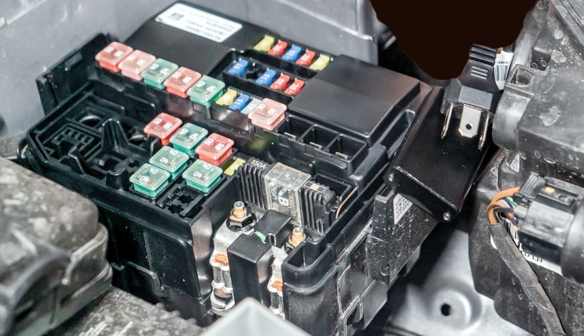
Blocks under the hood
General location
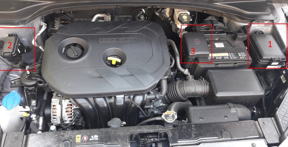
Main unit
It is located on the left side of the engine compartment.
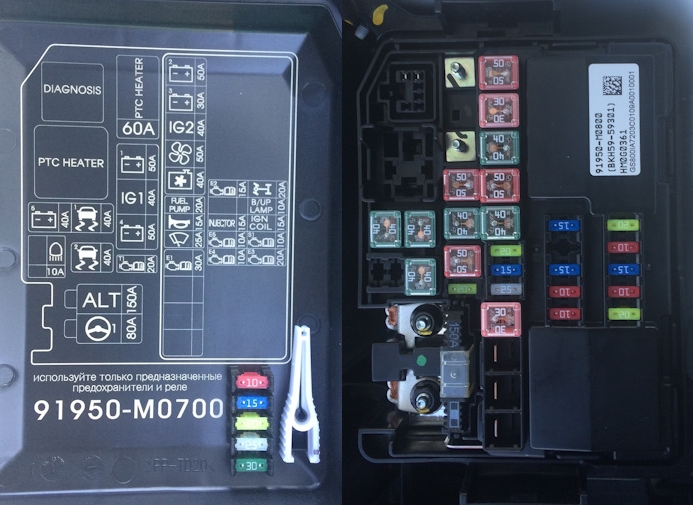
Marking
| MDPS | 80A MDPS (Power Steering Motor) |
| ALL | G4FC (125 A): generator, battery, all fuses connected to generator fuse D4FC / D4FB (150 A): generator, battery, all fuses connected to fuse |
| ECU2 | G4FC (10A): ECU (M/T), PCU (A/T) D4FC (15A): CAM SNSR, Glow RLY, WGT, EGR Control Valve, Air Flow SNSR, IMMOD4FB (15A): CAM SNSR, VGT Vacuum, IMMO |
| HEAD LAMP HIGH BEAM | High beam solenoid valve relay (dual-function type) |
| ABS2 | ABS/ESC control unit |
| ECU 4 | G4FC (25A): ECU (M/T), PCU (A/T) D4FC (15A): Meter Inlet Valve, D4FB (15A): Glow Plug Relay, Fuel Meter Unit |
| TCU 1 | D4FB: TCU (automatic transmission) |
| ONE+5 | Instrument panel fuse block fuse: FS01 |
| ABS 1 | ABS/ESC control unit, engine compartment diagnostics |
| ONE+4 | Instrument panel fuse block fuse: FS06, IPS-1, IPS-2, IPS-3 |
| IG1 | Without start button: Ignition SW With start button: PDM relay unit |
| ONE+1 | Instrument panel fuse block fuse: FS14, FS05, FS13, FS17, FS10, FS02, FS09, IOD relay (automatic leakage current cut-off) |
| GLOW | D4FC / D4FB: glow relay, glow plug |
| FUEL HEATER | D4FC / D4FB: Fuel heater |
| ECU 1 | (Engine control) Main relay |
| FRONT WIPER | Wiper motor (front) |
| HORN | Sound signal (double), burglar alarm sound signal |
| FUEL PUMP | G4FC: fuel pump relay, fuel pump motor |
| C/FAN | G4FC (40A), radiator fan motor D4FC / D4FB (50A) – radiator fan motor |
| BLOWER | Fan motor |
| IG2 | Without start button: start relay, start solenoid, ignition SW Start button: start relay, start solenoid, PDM relay block |
| ONE+3 | Instrument panel fuse block fuse: FS04, IPS-4, IPS-5 |
| ONE+2 | Fuse in the fuse box on the instrument panel: FS03, P / window relay, P / output relay |
| INJECTOR | G4FC: Injector (#1, #2, #3, #4) |
| BACK UP LAMP | Reverse switch (MT only), rear combination lamp, left/right |
| IGN COIL | G4FC: condenser, ignition coil, internal |
| SENSOR 1 | G4FC: Intake manifold solenoid, outlet camshaft (IN, EX), purge solenoid, oxygen sensor (UP, DN), IMMO D4FB: Lambda sensor, stops, EGR actuator, D4FC: stops |
| ECU 3 | D4FC / D4FB: ECU G4FC: ECU (M / T), PCU (A / T) |
| GLOW | D4FC / D4FB: Glow plug |
Some additional relays can be attached to the back of the unit.
Scheme
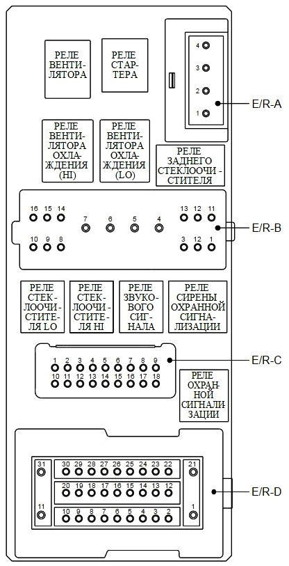
Additional unit
Depending on the equipment level, some Creta models will install an additional unit.
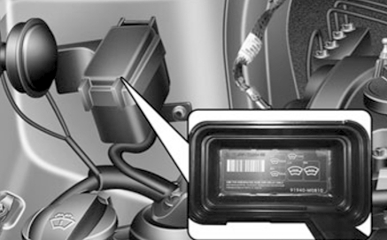
See the current diagram on the back of the cover. Here are the fuses and relays responsible for additional heating and glass de-icing.
There may also be high-capacity fuses on the positive terminal of the battery.