Mercedes w221 is the fifth generation of the S-class Mercedes-Benz, produced in 2005, 2006, 2007, 2008, 2009, 2010, 2011, 2012 and 2013 with various versions of S350, S450, S500, S600, S65 AMG, S63. During this time, the model was restyled. Our information will also be useful to owners of the Mercedes-Benz C216 (CL-class), since these cars are made on a common base. We will present a detailed description of the fuses and relays of the Mercedes 221 with block diagrams and their locations. We will highlight the fuses that are responsible for the cigarette lighter.

The location of the blocks and the purpose of the elements in them may differ from that shown and depends on the year of manufacture and the level of equipment of your car.
Blocks under the hood
Location
Mercedes 221 hood block layout diagram
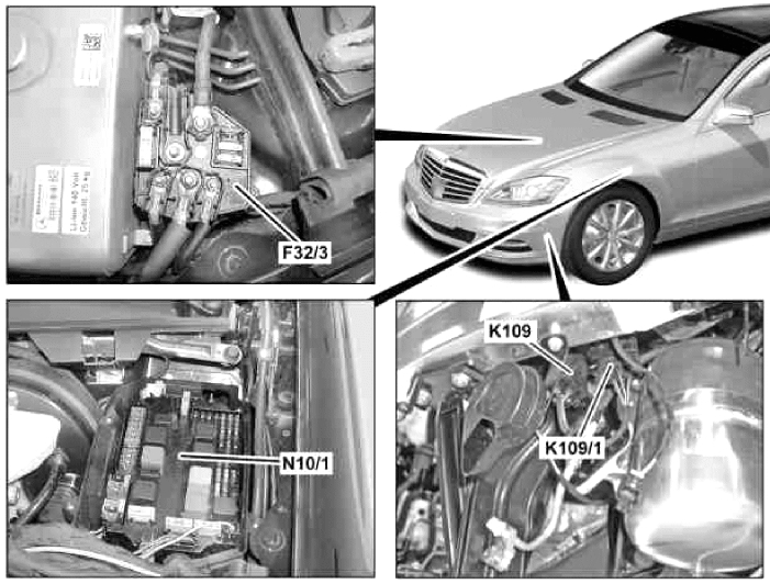
- F32/3 – Power fuse box
- N10/1 – Main fuse and relay box
- K109 (K109/1) – Vacuum pump relay
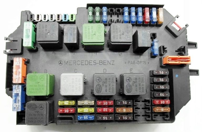
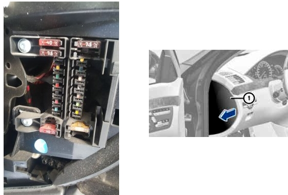
Fuse and relay box
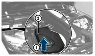
It is located on the left side, next to the stand and is covered with a protective cover.
Photo – example
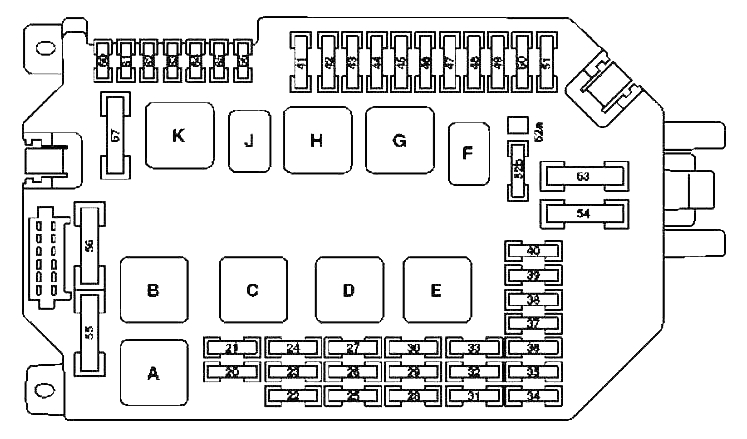
Designation
| 20 | 10A CDI System Control Unit |
| ME control unit | |
| 21 | 20A Cable Lug Electrical Circuit Terminals 87 M1i |
| CDI system control unit | |
| Fuel pump relay | |
| Dosing valve | |
| 22 | 15A Cable Lug Electrical Circuit Terminals 87 |
| 23 | 20A Cable Lug Electrical Circuit Terminals 87 |
| Cable lug electrical circuit terminals 87 M2e | |
| Cable lug electrical circuit terminals 87 M2i | |
| SAM control unit with fuse and relay module in the rear compartment | |
| 24 | 25A Cable Lug Electrical Circuit Terminals 87M1e |
| CDI system control unit | |
| 25 | 7.5A Instrument cluster |
| 26 | 10A Front left headlight |
| 27 | 10A Front Right Headlight |
| 28 | 7.5A |
| EGS control unit | |
| Control unit integrated into automatic transmission (VGS) | |
| 29 | 5A SAM control unit with rear fuse and relay module |
| 30 | 7.5A CDI System Control Unit |
| ME control unit | |
| Fuel pump control unit | |
| 31 | 5A S 400 Hybrid: Electric air conditioning compressor |
| 32 | 15A Control unit of additional gearbox oil pump |
| 33 | 5A From 1.9.10: ESP control unit |
| S 400 Hybrid: | |
| Battery management system unit | |
| DC/DC Converter Control Unit | |
| Power electronics control unit | |
| 34 | 5A S 400 Hybrid: Brake Energy Regeneration Control Unit |
| 35 | 5A Electric Parking Brake Control Unit |
| 36 | 10A Diagnostic socket |
| 37 | 7.5A EZS Control Unit |
| 38 | 7.5A Central Interface Control Unit |
| 39 | 7.5A Instrument cluster |
| 40 | 7.5A Upper Control Panel |
| 41 | 30A Slave Wiper Motor |
| 42 | 30A Main Wiper Motor |
| 43 | 15A Cigarette Lighter with Illuminator, Front |
| 44 | Reserve |
| 45 | 5A S 400 Hybrid: |
| Circulation pump 1 power electronic devices | |
| 46 | 15A ABC (Active Body Level Control) control unit |
| AIRMATIC control unit with ADS | |
| 47 | 15A Electric motor for adjusting the steering column up and down |
| 48 | 15A Electric motor for adjusting the steering column forward and backward |
| 49 | 10A Electronic Steering Column Module |
| 50 | 15A KLA Control Unit |
| 51 | 5A Display COMAND |
| Display of the split image system SPLITVIEW (split image system) | |
| 52a | 15A W221: |
| Left horn | |
| Right horn | |
| 52b | 15A W221, C216: |
| Left horn | |
| Right horn | |
| 53 | Reserve |
| 54 | 40A Air conditioning system air recirculation unit |
| 55 | 60A Petrol Engines: Electric Air Pump |
| 56 | 40A Compressor unit of the AIRmatic system |
| 57 | 30A Windscreen wiper heating |
| 60 | 5A Electro-hydraulic power steering |
| 61 | 7.5A Passive safety systems control unit |
| 62 | 5A Night Vision Control Unit |
| 63 | 15A Fuel filter condensate sensor with heating element |
| 64 | 10A W221: |
| NECK-PRO headrest solenoid coil on the driver’s seat back | |
| NECK-PRO headrest solenoid coil on the back of the right front seat | |
| 65 | 15A Valid from 1.6.09: 12 volt plug connection in glove compartment |
| 66 | 7.5A DTR Control Module (Distronic) |
| Relay | |
| A | Air pump relay |
| B | Air Suspension Compressor Relay |
| C | relay terminal 87, engine |
| D | Relay terminal 15 |
| AND | Electrical circuit relay terminal 87 chassis |
| F | Sound signal relay |
| G | Relay terminal 15R |
| H | Relay electrical circuit terminal 50, starter |
| J | Relay of electric circuit terminal 15, starter |
| K | Windscreen wiper heating relay |
The front cigarette lighter is controlled by fuse number 43 for 15A. The rear cigarette lighter is controlled by fuses in the rear fuse and relay box.
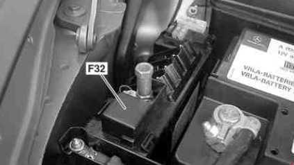
Power fuse box
Located on the right side of the engine compartment, next to the battery.
Option 1
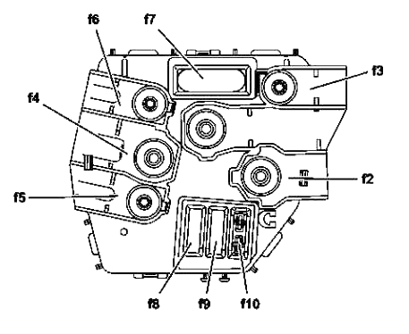
Scheme
Purpose
- F32f1 – Starter 400A
- F32f2 – Except Engine 642: Generator 150A / Engine 642: Generator 200A
- F32f3 – 150
- F32f4 – Suction electric fan of the engine and air conditioner with integrated regulator 150A
- F32f5 – Engine 642: Additional heater PTC 200A
- F32f6 – SAM control unit with fuse and relay module, front 200A
- F32f7 – ESP 40A control unit
- F32f8 – ESP control unit 25A
- F32f9 – SAM control unit with fuse and relay module, front 20A
- F32f10 – On-board network control unit 7.5A
Option 2
Photo
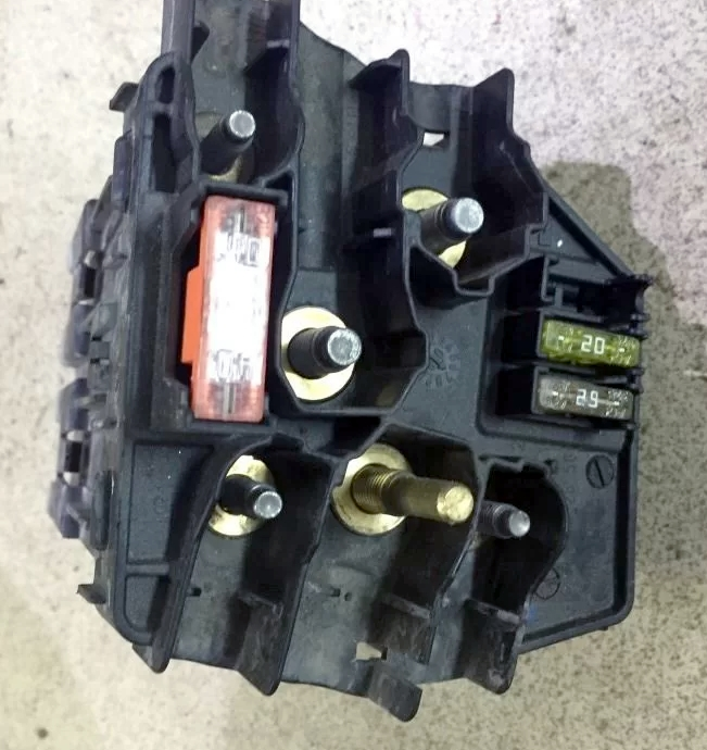
Designation
| 3 | 150A SAM Control Unit with Rear Fuse and Relay Module |
| 4 | 150A ECO Start-Stop function relay |
| S 400 Hybrid: DC/DC converter control unit | |
| Windscreen heating control unit | |
| 5 | 125A Multifunctional Special Vehicle Control Unit (MSS) |
| 40A S 400 Hybrid: Vacuum Pump | |
| 6 | 80A Right side fuse box in front panel |
| 7 | 150A Multifunctional Special Vehicle Control Unit (MSS) |
| Engine 629, 642, 651: PTC Additional Heater | |
| 8 | 80A Front SAM Control Unit with Fuse and Relay Module |
| 9 | 80A Left Fuse Box in Front Panel |
| 10 | 150A SAM Control Unit with Rear Fuse and Relay Module |
Blocks in the cabin
Location
Layout of blocks in the Mercedes 221 cabin
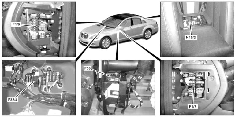
Transcript
- F1/6 – Fuse box in the instrument panel, right
- F1/7 – Fuse box in the instrument panel, left
- F32/4 – Power fuse box
- F38 – Emergency battery fuse
- N10/2 – Rear fuse and relay box
Fuse box in the panel on the left
This fuse box is installed on the left end of the instrument panel, behind the protective cover
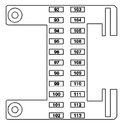
Transcript
| 92 | 40A Front left seat control unit |
| 93 | 7.5A Passive safety system control unit |
| Control unit for weight sensing system (WSS) (USA) | |
| 94 | Not used |
| 95 | Not used |
| 96 | 5A RDK control unit (tire pressure monitoring system (Siemens)) |
| 97 | 7.5A W221: Control unit Audio – Video – Controller (multimedia entertainment system in the rear compartment) |
| 98 | Not used |
| 99 | Not used |
| 100 | Not used |
| 101 | 10A Display left in the rear of the cabin |
| Display right in the rear of the cabin | |
| 102 | 40A Seat control unit front right |
| 103 | 7.5A ESP control unit |
| 104 | 40A Audio Tuner Control Unit |
| 105 | Not used |
| 106 | Electronic Toll Collection (ETC) Control Unit (Japan) |
| 107 | 5A C216: SDAR Control Unit |
| 108 | 5A Rear Air Conditioner Control Unit |
| 109 | 15A W221: Intermediate plug connection for rear electric fan |
| 110 | 7,5A W221: |
| Multicontour seat back control unit rear left | |
| Multicontour seat back control unit rear right | |
| 111 | 5A HBF Control Unit |
| 112 | 5A W221: |
| Front left door control unit | |
| Front right door control unit | |
| 113 | Not used |
Fuse box in the panel on the right
This fuse box is installed on the right end of the instrument panel on the left, behind the protective cover.
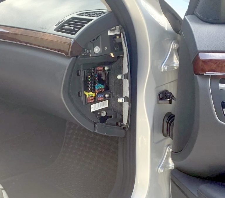
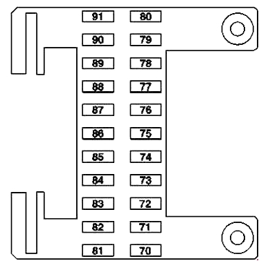
Description
| 70 | 40A C216: Right Door Control Unit |
| W221: Control unit in front right door | |
| 71 | 15A KEYLESS-GO Control Unit |
| 72 | 7.5A S 400 Hybrid: Pyrotechnic disconnecting element |
| 73 | 5A COMAND control unit (Japan) |
| Emergency call system control unit | |
| 74 | 30A HDS Control Unit (Remote Trunk Lid Closing) |
| 75 | 10A S 400 Hybrid: |
| Battery management system unit | |
| Power electronics control unit | |
| 76 | Engine 642.8: AdBlue® Supply Relay |
| 15A S 400 Hybrid: Vacuum Pump Relay (+) | |
| 77 | 50A Acoustic Amplifier |
| 78 | 25A S 65 AMG with 275 engine: Additional fan relay |
| Engine 642.8: AdBlue® Supply Relay | |
| 15A Engine 157, 278; S 400 Hybrid, CL 63 AMG: Charge air cooler circulation pump | |
| 79 | 7.5A Alarm Siren |
| 80 | 40A C216: Control unit in left door |
| W221: Control unit in front left door | |
| 81 | 30A C216: Rear compartment systems control unit |
| 40A W221: Rear left door control unit | |
| 82 | 30A C216: Rear compartment systems control unit |
| 40A W221: Rear right door control unit | |
| 83 | 30A Automatic transmission servo module for the “DIRECT SELECT” system |
| 84 | 20A Digital Sound Processor |
| 85 | 10A AMG: Illuminated door sills |
| 86 | Reserve |
| 87 | Reserve |
| 88 | Reserve |
| 89 | Reserve |
| 90 | 20A C216: STH heater (autonomous heating system) |
| W221: Heater STH (autonomous) or ZUH (additional) | |
| 91 | 5A Receiver unit for remote radio control of autonomous heater STH |
| S 400 Hybrid: Front control unit SAM with fuse and relay module |
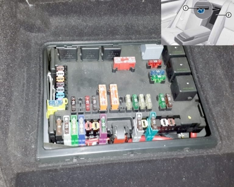
Rear fuse and relay box
This unit is installed in the luggage compartment, behind the rear seat armrest. To access it, lower the armrest and remove the protective cover.
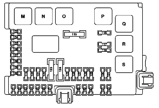
Designation
| 115 | 50A Rear Window Defogger |
| 116 | 10A Engine 157, 275, 278: Charge air cooler circulation pump |
| Engine 156: Engine Oil Cooler Circulation Pump | |
| S 400 Hybrid: Circulation pump 2 power electronics | |
| 117 | 15A Rear Cigarette Lighter |
| 118 | 30A Engine 629, 642: Fuel Pump |
| 15A S 400 Hybrid: Circulation pump 1 power electronics | |
| 15A Engine 642.8, 651 from 1.6.11: Refrigerant compressor with electromagnetic clutch | |
| 119 | 7.5A Central Control Panel Front |
| 120 | Reserve |
| 121 | 10A Audio Tuner Control Unit |
| 122 | 7.5A COMAND control unit |
| 123 | 40A W221: Front right reversible seat belt tensioner |
| 124 | 40A W221: Front left reversible seat belt tensioner |
| 125 | 5A Voice Buzzer (SBS) |
| 126 | 25A Ceiling Control Panel |
| 127 | 30A Seat Back Lower Pump |
| Multi-contour seat pneumatic pump | |
| Pneumatic pump for dynamic seat adjustment | |
| 128 | 25A Engine 156, 157, 272, 273, 275, 276, 278, 642: Fuel Pump Control Unit |
| 129 | 25A UHI(Universal Cell Phone Interface) Control Unit/Ceiling Control Panel |
| 130 | 30A Electric Parking Brake Control Unit |
| 131 | 7.5A Antenna Amplifier Module Above Rear Window |
| 133 | 15A Trailer Recognition Control Unit |
| 5A Rear view camera | |
| 134 | 15A Socket in the Luggage Compartment |
| 135 | 7.5A Sensor Radar Control Unit (SGR) |
| PTS control unit (PARKTRONIC) | |
| 136 | 7.5A Engine 642.8: AdBlue® Control Unit |
| 137 | 7.5A From 1.9.10: Rear view camera |
| 138 | 5A Navigation Processor (Taiwan, up to 8/31/10) |
| Emergency call system control unit | |
| TV/Tuner Plug Connection (Japan) | |
| 139 | 15A Cooling box in the back of the rear seat |
| 140 | 15A Cigarette lighter plug with ashtray lighting, rear |
| 115 V outlet | |
| 141 | 5A Rear View Camera Control Unit |
| Rear view camera power module | |
| 142 | 7.5A PTS control unit (PARKTRONIC) |
| Sensor Radar Control Unit (SGR) | |
| Control unit for video sensors and radar sensors (since 1.9.10) | |
| 143 | 25A Rear Seat Control Unit |
| 144 | 25A Rear Seat Control Unit |
| 145 | 20A AHV Towbar Plug, 13-Pin |
| 146 | 25A Trailer Recognition Control Unit |
| 147 | Reserve |
| 148 | 25A Terminal 30 Panoramic Sliding Sunroof End Sleeve |
| 149 | 25A Panoramic Sliding Sunroof Control Module |
| 150 | 7.5A Combo TV Tuner (Analog/Digital) |
| TV/Tuner Plug Connection (Japan) | |
| 151 | 20A Trailer Detection Control Module 25A Electric Parking Brake Control Module |
| 152 | 25A DC/AC Converter Control Unit 7.5A Antenna Amplifier Module Above Rear Window |
| Relay | |
| M | Relay terminal 15 (2) / reserve 1 (changeover contact relay) |
| N | Relay terminal 15R |
| THE | Socket relay |
| P | Rear window heating relay |
| Q | Engine 156, 157, 275, 278, 629: Circulation pump relay |
| S 400 Hybrid: Circulation pump relay 2 power electronics | |
| R | Cigarette lighter relay |
| S | Engine 642, except 642.8: Fuel pump relay |
| Engine 642.8, 651 from 1.6.11: Electromagnetic clutch of refrigerant compressor | |
| S 400 Hybrid: Circulation pump relay 1 power electronics | |
Fuse 117 and 134 are responsible for the cigarette lighter.
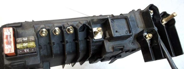
Power fuse box
In the passenger compartment, on the right side, on the passenger side, there is another block of power fuses.
Photo – example
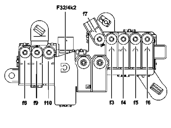
Purpose
| 2 | 400A Generator (G2) |
| 3 | 150A Electro-hydraulic power steering |
| Engine 629, 642:End of glow plug time | |
| 4 | Passenger compartment power fuse box F32/4 |
| 5 | 100A Electric suction fan for engine and air conditioner with integrated regulator |
| 6 | 150A Front SAM Control Unit with Fuse and Relay Module |
| 7 | 40A ESP control unit |
| S 400 Hybrid: Brake Energy Regeneration Control Unit | |
| 8 | 25A ESP control unit |
| S 400 Hybrid: Brake Energy Regeneration Control Unit | |
| 9 | 25A Front SAM Control Unit with Fuse and Relay Module |
| 10 | Reserve |
| Relay | |
| F32/4k2 | Quiescent current cut-off relay |