Hyundai Matrix subcompactvan is also known in some countries as Hyundai Lavita. It was produced with gasoline engines of 1.5 1.6 1.8 liters. Years of production: 2001, 2002, 2003, 2004, 2005, 2006, 2007, 2008, 2009 and 2010. During this time, the Matrix has undergone restyling twice. In this material you will find a description of the fuses and relays of the Hyundai Matrix with block diagrams and photo examples of their location. We will note the cigarette lighter fuse. We will also show the location of all electronic control units.
Control units
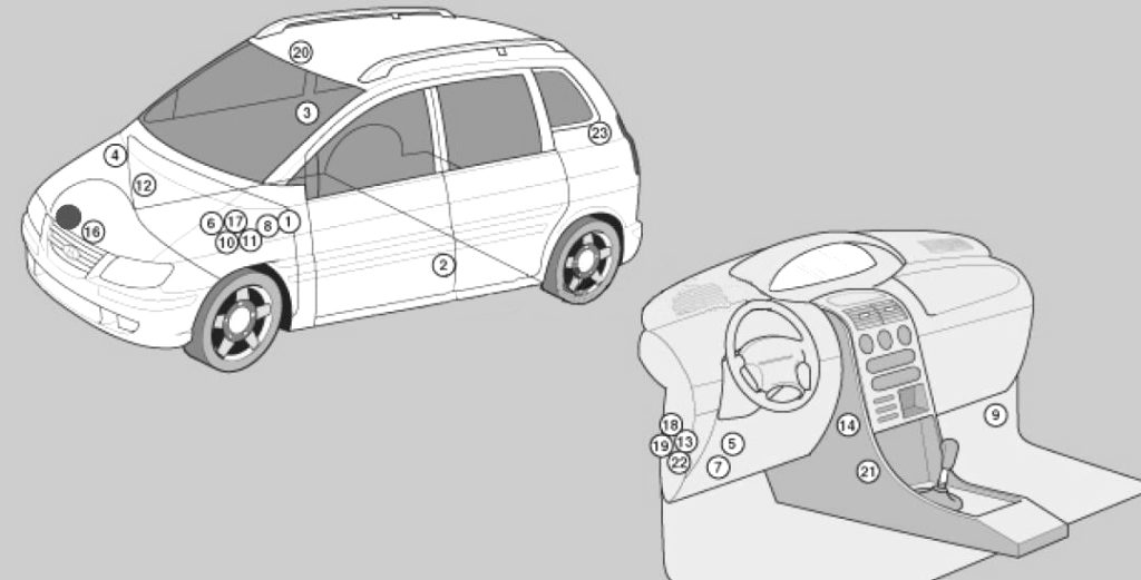
General layout of electronic control units
Appointment
| 1 | ABS electronic control unit |
| 2 | Side impact sensor, left — B-pillar |
| 3 | Side impact sensor, right — Center pillar |
| 4 | Anti-theft system siren – bulkhead |
| 5 | Audible warning signal / buzzer – behind the fuse / relay box of the instrument panel |
| 6 | Rechargeable battery |
| 7 | Diagnostic connector (DLC) – under the instrument panel |
| 8 | Daytime running light control unit – inner wing |
| 9 | Electronic engine control unit – lower protective panel |
| 10 | Fuse/relay block, engine compartment 1 |
| 11 | Fuse/relay block, engine compartment 2 (Diesel) |
| 12 | Fuse/relay block, engine compartment C (Diesel) |
| 13 | Fuse/relay block, instrument panel |
| 14 | Heater fan motor resistor – next to the heater fan motor |
| 15 | Audible signal (upper) |
| 16 | Beep (bottom) |
| 17 | Fuel cut-off inertia switch – behind the battery |
| 18 | Immobilizer control unit – behind the instrument panel fuse/relay block |
| 19 | Multifunction control unit – behind the fuse box / relays of the dashboard – functions anti-theft system, central locking, rear window heater, buzzer for the presence of a key in the ignition lock, interior lights / delay switch-off, seat belt warning system |
| 20 | The sunroof electric drive relay is on the ceiling panel. |
| 21 | SRS electronic control unit – under the center console |
| 22 | Electronic gearbox control unit – automatic transmission – behind the instrument panel, on the left |
| 23 | Rear window wiper relay – left side of luggage compartment |
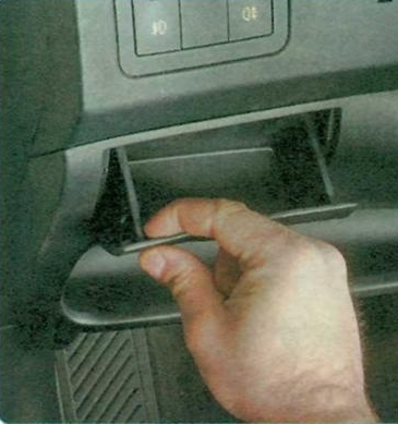
Block in the Hyundai Matrix cabin
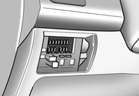
Located at the bottom of the instrument panel. Remove the cover to access.

Relay description
- Reserve
- Central locking relay (unlock)
- Alarm relay
- Reserve
- Central locking relay
- Power window relay
- Anti-theft system relay
- Anti-theft siren relay
- Rear window heater relay
- Turn signal relay-interrupter
- Heater fan motor relay
There are several possible options for designing a fuse compartment.
Schemes

Fuse designations
| RR HTD | 30A Rear window defroster relay |
| STOP | 10A Brake light relay, power window relay |
| D/LOCK | 15A Door lock (unlock) relay, ETASM, sunroof relay |
| HAZARD | 10A Burglar alarm relay, emergency alarm relay |
| AUDIO | 10A Car radio |
| C/LIGHT | 15A Cigarette lighter |
| A/B | 10A Airbag control unit |
| A/В IND | 10A Airbag warning light |
| T/SIG | 10A Hazard warning switch, seat belt timer, instrument panel, ABS control unit, excitation resistor, washer pump drive |
| ECU | 15A ECM, vehicle speed sensor, fuel pump, ignition coil |
| ETACS | 10A ETASM, automatic transmission selector |
| RRWPR | 10A Rear wiper motor, rear wiper relay |
| START | 10A Starter Relay |
| FRTWPR | 20A Wiper relay, washer pump motor, wiper timer and rear window heater |
| S/HTD | 15A Left (right) front seat heating switch |
| P/OUTLET | 25A Front (rear) socket for connecting external consumers |
| IG2 | 10A ETASM, power window relay, rear window heater relay, sunroof relay, headlight relay, heating and air conditioning fan relay |
| O/S MRR | 10A Exterior mirror switch, rear fog light relay |
The fuse responsible for the front cigarette lighter is marked C/LIGHT, and for the additional sockets P/OUTLET.
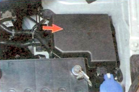
Blocks under the hood of Hyundai Matrix
Main unit
It is located next to the battery under a protective cover.
Example of a circuit from the cover

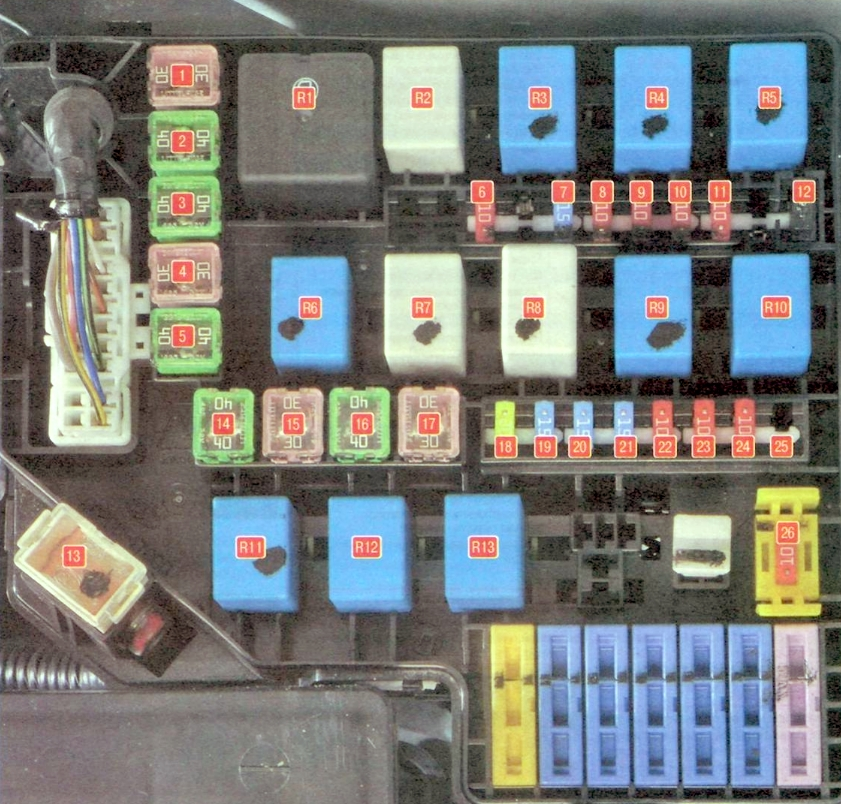
Transcript
| 1(30) | COND – Condenser electric fan |
| 2(40) | ABS – ESP stability control system and ABS anti-lock braking system |
| 3(40) | ABS – ESP stability control system and ABS anti-lock braking system |
| 4(30) | P/WIN – Power windows |
| 5(40) | BLR – Electric heater radiator fan |
| 6(10) | ABS – Anti-lock braking system ABS |
| 7(15) | INJ – Fuel injectors, ignition coils |
| 8(10) | SNSR – Engine Management System Sensors |
| 9(10) | F/PUMP – Fuel pump |
| 10(10) | TAIL LH – Left tail light, left license plate light |
| 11(10) | TAIL RH Right tail light, right license plate light |
| 12 H | Rear fog light activation diode |
| 13(120) | VAT – Generator |
| 14(40) | B+ – Air conditioning, heated rear window, brake lights, central locking, anti-theft alarm |
| 15(30) | ECU – Engine Control Unit, Generator, Main Relay of the Engine Management System |
| 16(40) | IGN – Starter, ignition switch (lock) |
| 17(30) | RAD – Electric radiator fan |
| 18(20) | TAIL – Tail lights |
| 19(15) | FR FOG – Fog lights |
| 20(15) | H/LP LH – Left headlight |
| 21(15) | RH – Right headlight |
| 22(10) | ECU – Engine Control Unit, Generator, Main Relay of the Engine Management System |
| 23(10) | HORN – Sound signal |
| 24(10) | A/CON – Air conditioning |
| 25(15) | DRL – Daytime Running Light Control Unit |
| 26(10) | ROOM LP – Car radio, interior lighting, instrument cluster illumination |
| R1 | MAIN – Main relay |
| R2 | COND2 – Condenser electric fan relay (low speed) |
| R3 | F/P CHK – Fuel Pump Relay |
| R4 | RAD – Radiator fan relay |
| R5 | H/LP – Headlight On Relay |
| R6 | HORN – Horn relay |
| R7 | WIPER – Wiper Relay |
| R8 | R/W DIODE – Diode on relay (pos. 12) |
| R9 | START – Starter relay |
| R10 | A/CON – Air conditioning relay |
| R11 | TAIL – Taillight relay |
| R12 | COND1 – Condenser electric fan relay (high speed) |
| R13 | FR FOG – Rear fog light relay |
Additional unit
Scheme
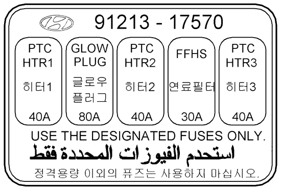
Description
- GLOW – candles
- PTC – additional heater