Toyota Land Cruiser 100 and Toyota Land Cruiser 105 were produced in 1998, 1999, 2000, 2001, 2002, 2003, 2004, 2005, 2006, 2007. During this time, the model was restyled. In this publication, we will show the location of electronic control units, a description of fuses and relays Toyota Land Cruiser 100 (105) with block diagrams and their locations. We will highlight the cigarette lighter fuse.
The arrangement of the blocks and the purpose of the elements in them may differ from the one shown and depends on the year of manufacture and the region of delivery. Check the purpose with your diagrams on the block cover.
Blocks in the cabin
Location
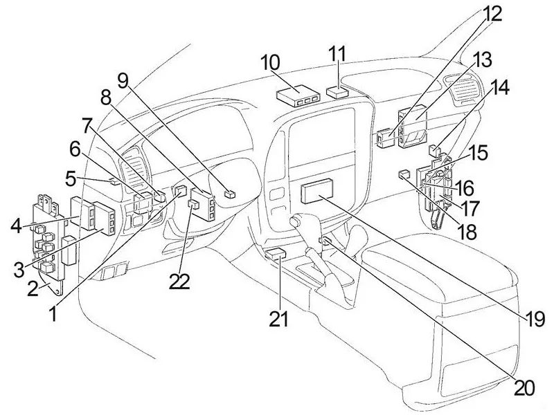
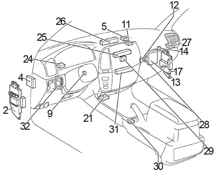
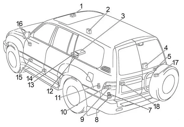
General layout of the units in the cabin
Left hand drive (1998 – 2002)
- ’98-’02: Turn signal relay
- ’98-’02: Fuse Box
’02-’07: Fuse Box / Body Electronics Box - ’98-’02: ABS Control Unit
- Steering column adjustment control unit
- Key transponder computer
- ’98-’02: Door Lock Control Unit
- ’98-’02: Electronic Toll Collection Block
- ’98-’02: Suspension Control Unit
- Key transponder amplifier
- ’98-’02: Instrument Panel Control Unit
- Anti-theft system control unit
- Automatic Antenna Relay
- Engine and gearbox control unit
- Interaxle differential lock relay
- ’98-’02: Front and rear differential lock control unit
or
Rear differential lock control unit - ’98-’02: Cruise Control Unit
- ’98-’02: Distribution Block (MTR Relay)
’02-’07: Fuse Block - ’98-’02: Auxiliary heater control unit
- ’98-’02: Central control unit
- ’98-’02: Deceleration Sensor
- Central airbag unit
- ’98-’02: Active Height Control (AHC) Relay
- ’98-’02: Right hand drive : Heating timer
- ’02-’07: Air conditioning control unit (if equipped with navigation)
- ’02-’07: Distribution Block
- ’02-’07: Distribution Block
- ’02-’07: Distribution Block
- ’02-’07: Distribution Block
- ’02-’07: Network Gateway Block
- ’02-’07: Gear selector lock control unit
- ’02-’07: Air conditioning control unit (without navigation)
- ’02-’07: ABS & BA & TRAC & VSC control unit
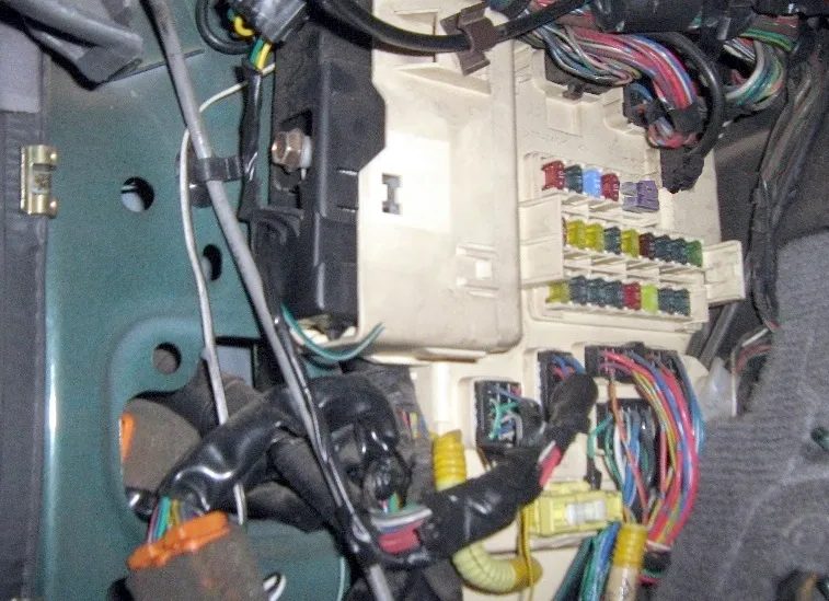
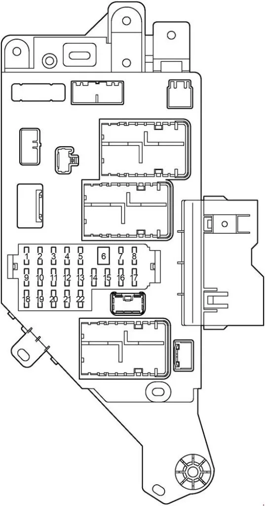
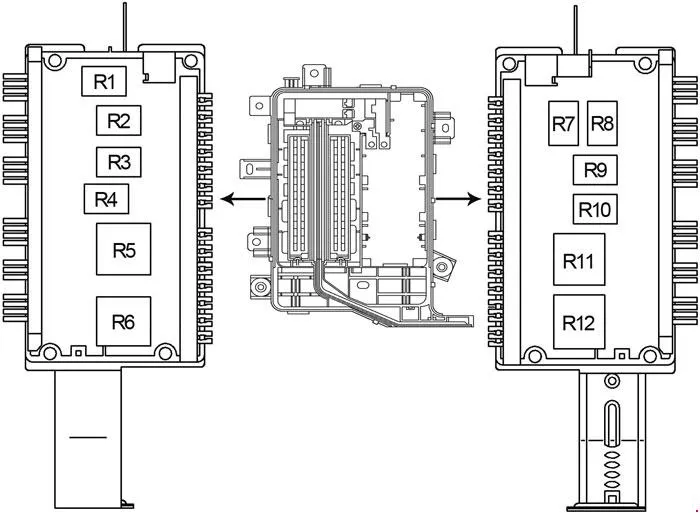
Fuse box on the left side
On the general diagram it is marked as number 2.
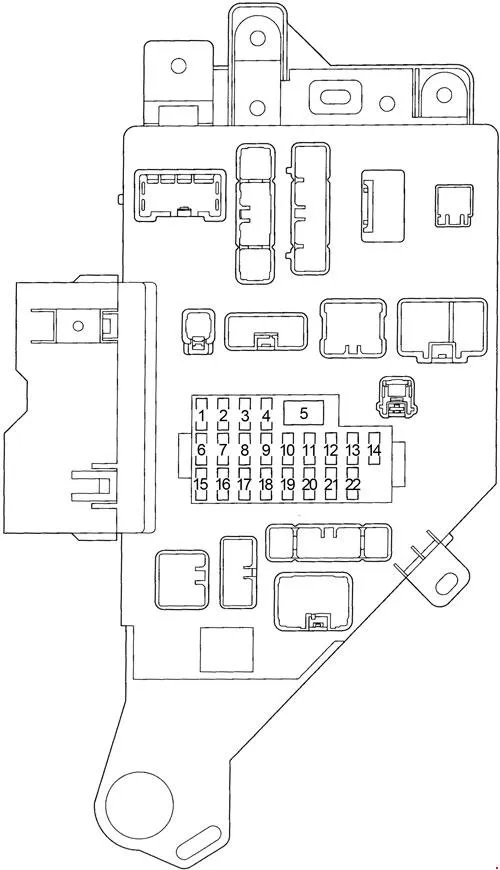
| 1 | 10A MIRR – Power Mirrors |
| 2 | 15A SRS – Airbags, seat belts with pretensioners |
| 3 | 15A CIGAR – Cigarette lighter , audio system, antenna |
| 4 | 10A IGN – Multiport fuel injection system/sequential multiport fuel injection system, ABS, air bags, seat belts with pretensioners, low battery warning light |
| 5 | 40A POWER – Central locking, power windows, sunroof, electric seats, tilt and height steering column adjustment |
| 6 | 10A DOME – Interior lighting, personal lighting |
| 7 | 20A AHC-IG – Active Height Control (AHC) |
| 8 | 20A DIFF – Differential Lock Control Unit |
| 9 | 15A GAUGE – Instrument cluster, service and warning indicators, warning buzzer, reversing lights, air conditioning, transmission control unit, daytime running lights, wireless control system |
| 10 | 20/25A WIPER – Windscreen wiper and washer, rear window wiper and washer |
| 11 | 7.5A I/UP – Engine Idle Speed System |
| 12 | 15A FR FOG – Front fog light |
| 13 | 15A STOP – Brake light bulbs, additional brake light |
| 14 | 30A RR AC – Rear Air Conditioner |
| 15 | 20A DEFOG – Rear Window Defogger |
| 16 | 15A ECU-B – Tilt and height steering column adjustment system, daytime running lights, anti-theft alarm system |
| 17 | 15A TAIL – Side light, number plate light, instrument panel light |
| 18 | 15A AHC-B – Active Height Control (AHC) |
| 19 | 10A OBD – Diagnostic connector |
| 20 | 10A RR HTR – Rear heater |
| 21 | 15A ECU-IG – ABS, gear selector lock, power seats, antenna, tilt and height steering column adjustment |
| 22 | 15A PWR OUTLET |
Fuses number 3 and 22, rated at 15A, are responsible for the operation of the cigarette lighter and socket.
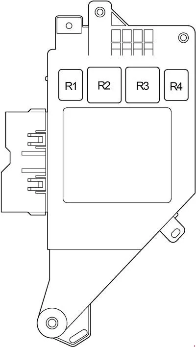
Some relays are attached to the back of the block.
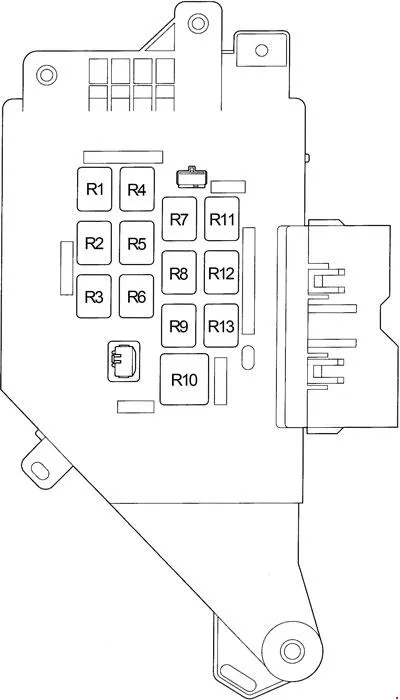
| R1 | Fuel pump (C/OPN) |
| R2 | Fuel pump (FUEL/PMP) |
| R3 | (D/L (L)) |
| R4 | (SPIL/VLV) |
| R5 | Starter (ST/CUT) |
| R6 | (D/L (U)) |
| R7 | Front fog light (FR FOG) |
| R8 | – |
| R9 | Rear window heating (DEFOG) |
| R10 | Power windows, sunroof (POWER) |
| R11 | Rear Heater (RR HTR) |
| R12 | Interior lighting (DOME) |
| R13 | Side light (TAIL) |
Scheme. Option 2.
2003 – 2007
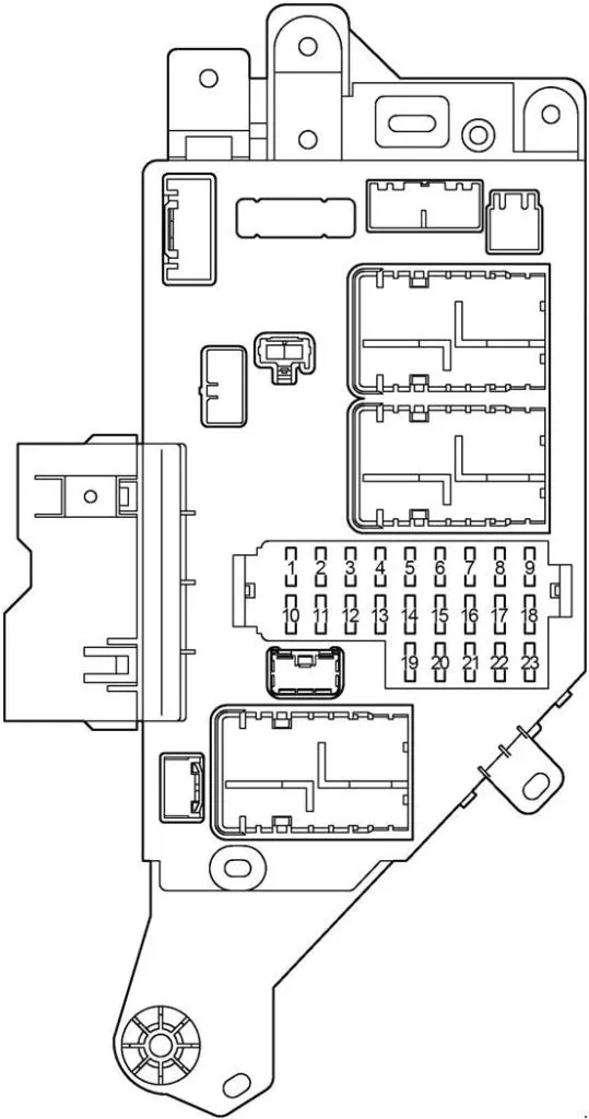
| 1 | 15A PWR OUTLET |
| 2 | 15A CIG – Cigarette Lighter |
| 3 | 7.5A ACC – Instrument cluster lighting |
| 4 | 7.5A AM1 – Multiport fuel injection system/sequential multiport fuel injection system |
| 5 | 20A DEFOG – Rear Window Defogger |
| 6 | 15A AHC−B – Active Height Control (AHC) |
| 7 | 20A FUEL HTR – Fuel Heating |
| 8 | 7.5A POWER HTR – Auxiliary Heater |
| 9 | 20A AHC−IG – Active Height Control (AHC) |
| 10 | 10A EFI NO.2 – Emission Control System |
| 10A ECD NO.2 – Emission Control System | |
| 11 | 10A GAUGE1 – Instrument Cluster |
| 12 | 10A ECU−IG1 – Multiport fuel injection system/sequential multiport fuel injection system |
| 13 | 10A ECU−B1 – Navigation system |
| 14 | 15A DBL LOCK – Double locking system |
| 15 | 30A BATT CHARGE – Trailer Charging System |
| 16 | 15A A/C – Air Conditioner |
| 17 | 15A STOP – Brake light bulbs |
| 18 | 7.5A OBD−2 – Diagnostic connector |
| 19 | 7.5A IDEL UP – Engine Idle Speed System |
| 20 | 30A LH SEAT – Left seat electric drive |
| 21 | 25A DOOR – Central locking, power windows |
| 22 | 25A SUN ROOF – Hatch |
| 23 | 15A RR WIPER – Rear Windscreen Wiper |
Fuses number 1 and 2, rated at 15A, are responsible for the operation of the cigarette lighter and socket.
Relay diagram from the back of the unit
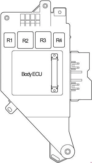
- R1 – Rear window heating (DEFOG)
- R2 – Ignition (IG1 NO.2)
- R3 – Ignition (ACC)
- R4 – Interior lighting (DOME)
Fuse box on the right side
On the diagram it is marked as number 17. It is located under the instrument panel.
Scheme
2002 – 2007
| 1 | 10A ECU−B2 – Central locking, window lifts |
| 2 | 20A DIFF – All-wheel drive system |
| 3 | 15A WASHER – Glass washer |
| 4 | 10A RADIO – Audio system |
| 5 | 10A DOME – Interior Lighting |
| 6 | 40A VGRS – Variable Gear Ratio Steering |
| 7 | 20A P/W (FL) – Front Left Window Regulator |
| 8 | 20A P/W (RL) – Rear Left Power Window |
| 9 | 25A WIPER – Windscreen wiper |
| 10 | 10A ECU−IG2 – Rear Air Conditioner |
| 11 | 15A SEAT HTR – Heated Seats |
| 12 | 10A GAUGE2 – Reverse Lights |
| 13 | 7.5A MET – Instrument cluster |
| 14 | 7.5A ING – Multi-point fuel injection system/sequential multi-point fuel injection system |
| 15 | 7.5A SECURITY – Anti-theft system |
| 16 | 20A P/W (RR) – Rear Right Window Regulator |
| 17 | 20A P/W (FR) – Front Right Window Regulator |
| 18 | 30A BATT CHARGE – Trailer Charging System |
| 19 | – |
| 20 | 20A TIL&TEL – Tilt and height adjustment system for the steering column |
| 21 | 30A RR A/C – Rear Air Conditioner |
| 22 | 30A RH SEAT – Right seat electric drive |
Relay diagram from the back of the unit
- R1 – Stop light lamps (STOP LP)
- R2 –
- R3 – Ignition (IG1 NO.3)
- R4 – Ignition cut-off (ACC CUT)
Additional elements
Scheme
- Hatch control unit
- RHD: Power Mirror Control Unit
- Audio system amplifier
- Air conditioner booster
- Rear Fan Relay
- Option 1: Rear wiper relay
- Hitch relay
- Trailer relay
- Fuel pump control unit
- Fuel pump select relay
- Additional fuel pump forced activation relay
- ’02-’07: Rear View Monitor Control Unit
- ’02-’07: Navigation control unit
- Rear Heater Relay
- Control valve
- LHD: Power Mirror Control Unit
- Option 2: Rear Right Windscreen Wiper Relay
- Option 2: Rear Left Windscreen Wiper Relay
Blocks under the hood
Location
General layout of the blocks under the hood
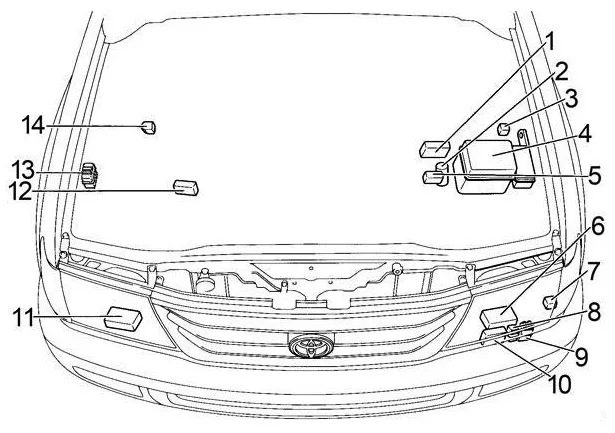
- Injector Control Unit (EDU)
- Main winch relay
- Glow Plug Relay
- Fuse and relay box
- Power fuse box
- Left headlight control unit
- Auxiliary heater relay
- Coolant Temperature Switch Relay
- Air conditioner fan relay
- Headlight Washer Relay
- Right headlight control unit
- Power fuse box (cold zone)
- Daytime running lights relay #3
- Intake Heater Relay
Fuse and relay box
Located on the left side, next to the battery.
Option 1
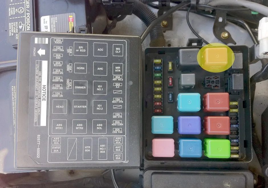
| Fuses | |
| 1 | 20A AM1 NO.2 – Starting system, direction indicators, hazard warning lights, fuses: ”CIGAR”, ”ECU−IG”, ”MIRR”, ”SRS” |
| 2 | 20A AC – Air Conditioner |
| 3 | 10A POWER HTR – Auxiliary Heater |
| 4 | 15A SEAT HTR – Heated Seats |
| 5 | 20A FUEL HTR – Fuel Heating |
| 6 | 15A MIR HTR – Heated Mirrors |
| 7 | 20A HEAD CLNER – Headlight Cleaners |
| 8 | 20A CDS FAN – Cooling system fan |
| 9 | 20A EFI – Multiport fuel injection system/sequential multiport fuel injection system, emission control system, fuel pump |
| 20A ECD – Multiport fuel injection system/sequential multiport fuel injection system | |
| 10 | 10A HORN – Horn |
| 11 | 15A THROTTLE – Electronic throttle control system |
| 12 | 20A RADIO – Audio system |
| 13 | 15A HAZ-TRN – Hazard warning lights, direction indicators |
| 14 | 30A AM2 – Starting system, multipoint fuel injection system/sequential multipoint fuel injection system, fuse ”IGN” |
| 15 | 20A ECU-B1 – Central locking, power windows, rear wiper and washer, wireless control system, electric mirrors, instrument cluster, air conditioning, automatic lighting system, anti-theft system |
| 16 | 20A HEAD (LH-UPR) – Left High Beam |
| 17 | 20A HEAD (RH-UPR) – Right High Beam |
| 18 | 10A HEAD (LH-LWR) – Low beam left, front fog light |
| 19 | 10A HEAD (RH-LWR) – Low beam right |
| 20 | 40A 1998-1999: ABS |
| 50A 2000-2003: ABS | |
| 21 | 50A AHC – Active Height Control (AHC) |
| 22 | 50A ACC – Fuse “PRW OUTLET” |
| 23 | 80A AM1 NO.1 – Charging system, fuses: ”AM1 NO.2”, ”GAUGE”, ”WIPER” |
| 24 | 60A HTR – Air conditioning |
| 25 | 80A GLOW – Engine pre-heating system |
| 26 | 40A ABS |
| 27 | 30A STARTER – Starting system |
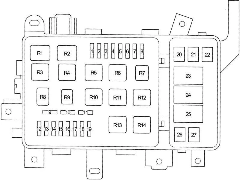
| Relay | |
| R1 | Air Conditioning Compressor Clutch (MG CLT) |
| R2 | Heated mirrors (MIR HTR) |
| R3 | Auxiliary relay (ACC) |
| R4 | Active Height Control (AHC) |
| R5 | Ignition (IG1 NO.1) |
| R6 | Ignition (IG1 NO.2) |
| R7 | ABS (ABS SOL) |
| R8 | Engine Control Unit (EFI) |
| Engine Control Unit (ECD) | |
| R9 | Sound signal |
| R10 | Dimmer (light switch) |
| R11 | Starter |
| R12 | ABS (ABS MTR2) |
| R13 | Headlights (HEAD) |
| R14 | ABS (ABS MTR1) |
Option 2
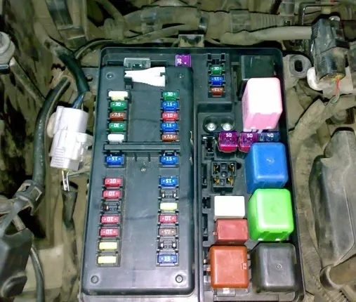
| 1 | – |
| 2 | – |
| 3 | – |
| 4 | – |
| 5 | 7.5A ST1 – 2002-2005: Multiport fuel injection system/sequential multiport fuel injection system |
| 7.5A WIP−S – 2006-2007: – | |
| 6 | 30A TOWING – Trailer Lighting |
| 7 | 15A MIR HTR – Heated Mirrors |
| 8 | 10A RR HTR – Rear heater |
| 9 | 15A HAZ−TRN – Hazard warning lights, direction indicators |
| 10 | 7.5A ALT−S – Charging system |
| 11 | 20A NV-IR |
| 12 | 15A FR FOG – Fog light |
| 13 | 30A TOWING BRK – Trailer Lighting (Brake Lights) |
| 14 | 20A HEAD CLNER – Headlight Cleaners |
| 15 | 10A FR−IG – Charging system |
| 16 | 7.5A PANEL – Instrument panel lighting |
| 17 | 30A TOWING TAIL – Trailer lighting (side light) |
| 18 | 15A TAIL – Side light |
| 19 | 30A BAT – Fuse: “ECU−B2” |
| 20 | 7.5A TEL – Telephone |
| 21 | 30A AMP – Audio system |
| 22 | 25A EFI NO.1 – Multiport fuel injection system/sequential multiport fuel injection system |
| 25A ECD NO.1 – Multiport fuel injection system/sequential multiport fuel injection system | |
| 23 | 15A AM2 – Fuse: “IGN” |
| 24 | 10A ETCS – Multiport fuel injection system/sequential multiport fuel injection system |
| 25 | 10A HORN – Horn |
| 26 | – |
| 27 | 10A HEAD (RH−LWR) – Low beam right |
| 28 | 10A HEAD (LH−LWR) – Low beam left |
| 29 | 20A HEAD (RH−UPR) – Right High Beam |
| 30 | 20A HEAD (LH−UPR) – Left High Beam |
| 31 | 40A ABS |
| 32 | 50A ABS |
| 33 | 50A AHC – Active Height Control (AHC) |
| 34 | 30A STARTER – Starting system |
| 35 | SHORT PIN A – Fuses: “BAT”, “AMP” |
| 36 | SHORT PIN B – Fuses: “HAZ-TRN”, “ALT-S” |
| 37 | 80A GLOW – Engine pre-heating system |
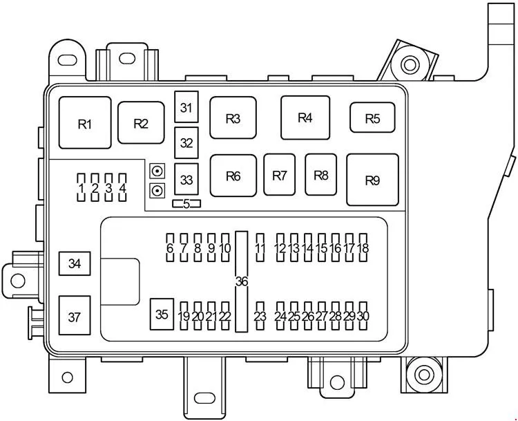
| Relay | |
| R1 | Heater (HTR) |
| R2 | ABS (ABS MTR1) |
| R3 | ABS (ABS MTR2) |
| R4 | ABS (ABS SOL) |
| R5 | Engine Control Unit (EFI) |
| Engine Control Unit (ECD) | |
| R6 | Active Height Control (AHC) |
| R7 | Fuel pump (C/OPN) |
| R8 | Fuel pump (F/PUMP) |
| R9 | Starter (ST) |
Relay
Scheme
| R1 | Coolant Temperature Switch Relay |
| R2 | Air Conditioning Compressor Clutch (MG CLT) |
| R3 | Cooling system fan (CDS FAN) |
| R4 | Sound signal |
| R5 | Headlights (HEAD) |
| R6 | High beam (HEAD HI) |
| R7 | Heated mirrors (MIR HTR) |
| R8 | Rear Heater (RR HTR) |
| R9 | Instrument panel lighting (PANEL) |
| R10 | Front fog light (FR FOG) |
| R11 | Ignition (IG NO.1) |
| R12 | Side light (TAIL) |
Block on the battery
A fuse block made in the form of fusible links is attached to the positive terminal of the battery.
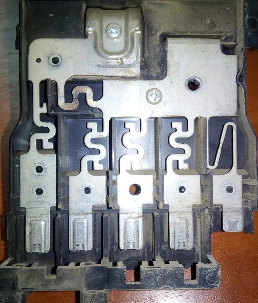
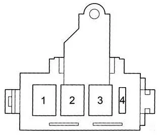
| 1 | 100A J/B NO.2 – Fuses: “ECU-B”, “FR FOG”, “DEFOG”, “AHC-B”, “TAIL”, “STOP”, “DOME”, “POWER”, “OBD”, “RR AC” and “RR HTR” |
| 2 | 140A ALT – Fuses: ”J/B NO.2”, ”MIR HTR”, ”AM1 NO.1”, ”ACC”, ”CDS FAN”, ”HTR” and ”ABS NO.1” |
| 3 | 100A MAIN – Fuses: “ECU-B”, “FR FOG”, “DEFOG’, “AHC-B”, “OBD”, “TAIL”, “STOP”, “DOME\ TOWER”, “RR AC”, “RR HTR” |
| 4 | 7.5A ALT-S – Charging System |
Option 2
2003 – 2007
| 1 | 50A HTR – Air Conditioner/Heater |
| 2 | 120A J/B NO.1 – Relay “IG1 NO.1”, Relay “TAIL”, Fuses: “MIR HTR”, “RR HTR”, “TOWING BRK”, “TOWING”, “FR FOG” |
| 3 | 120A J/B NO.2 – Relay “IG1 NO.2”, Relay “ACC”, Fuses: “DEFOG”, “AM1”, “LH SEAT”, “STOP”, “ECU-B1”, “SUN ROOF”, “OBD-2”, “DOOR” |
| 4 | 120A J/B NO.3 – Relay “IG1 NO.3”, fuses: “SECURITY”, “TIL & TEL”, “RH SEAT”, “RR A/C”, “P/W (RR)”, “P/W (RL)”, “P/W (FR)”, “P/W (FL)” |
| 5 | 120A MAIN – “HEAD HI” relay, “HEAD” relay, fuses: “ABS NO.1”, “ABS NO.2”, “SHORT PIN A”, “EFI OR ECD NO.1”, “SHORT PIN B”, “AM2”, “STARTER”, “HORN”, “ECTS” |
| 6 | 140A ALT – Fuses: “J/B NO.1”, “J/B NO.2”, “J/B NO.3”, “HTR” |