Mitsubishi Pajero Sport 2nd generation was produced in 2008, 2009, 2010, 2011, 2012, 2013, 2014, 2015 and 2016. In some countries of the world it is also known as Montero Sport 2/ Challenger (KG / KH / PB). In our material we will present a description of the fuses and relays of the Mitsubishi Pajero Sport 2nd generation with block diagrams and their locations. We will highlight the cigarette lighter fuse.

Depending on the year of manufacture, region of delivery and level of equipment, there may be differences between the presented material and your Mitsubishi Pajero Sport 2. Check the purpose with your technical documentation.
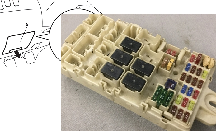
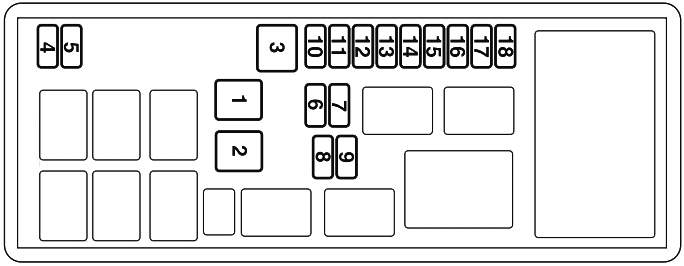
Cabin block
Located at the bottom of the instrument panel on the driver’s side behind a protective cover.
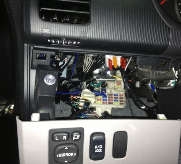
Block location
Scheme
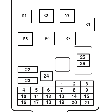
Fuse description
| 1 | 7.5A Side lights (left) |
| 2 | 15A Cigarette lighter |
| 3 | 10A Ignition coil |
| 4 | 7.5A Starter |
| 5 | 20A Roof hatch |
| 6 | 15A Socket |
| 7 | 7.5A Side lights (right) |
| 8 | 7.5A Exterior mirrors |
| 9 | 7.5A Engine control unit |
| 10 | 7.5A Control unit |
| 11 | 10A Rear fog light |
| 12 | 15A Central lock |
| 13 | 10A Interior light |
| 14 | 15A Rear window wiper |
| 15 | 7.5A Dashboard |
| 16 | 7.5A A/C compressor relay, A/C condenser fan relay, fan relay, heater controller, rear fan relay, rear cooler control panel, rear fan switch and rear window defroster relay |
| 17 | 20A Seat heating |
| 18 | 10A accessory power supply |
| 19 | 7.5A Heated exterior mirrors |
| 20 | 20A Janitors |
| 21 | 7.5A Reversing lights |
| 22 | 30A Heated rear window |
| 23 | 30A Heater |
| 24 | 40A Power seats |
| 25 | 10A Audio system |
| 26 | 15A Electronic control unit |
Fuses numbered 2 and 6, as well as relay numbered 2, are responsible for the operation of the cigarette lighter and power outlets.
Relay designation
- R1 – Seat heating relay
- R2 – Auxiliary equipment socket power relay
- R3 – Rear fog light relay
- R4 – Reserve
- R5 – Fan relay
- R6 – Rear window heating relay
- R7 – Reserve
Block under the hood
It is installed in the left side of the engine compartment next to the battery.
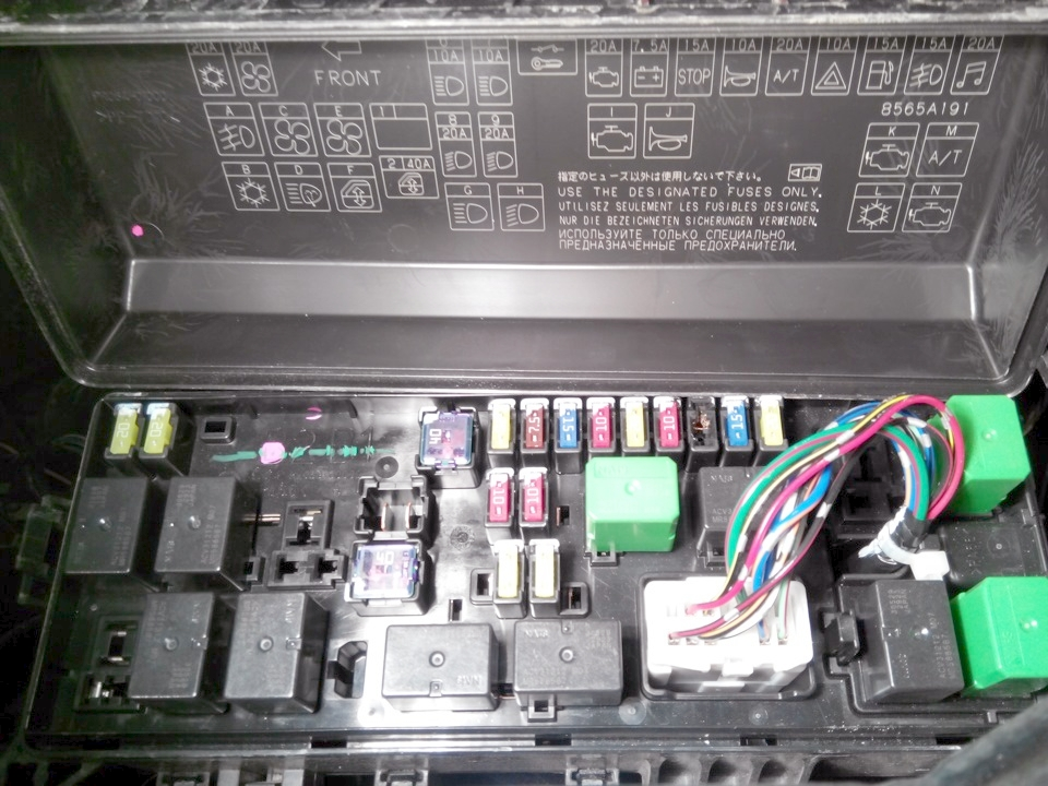
Fuse diagram
Purpose of fuses
| 1 | Reserve |
| 2 | 40A Electric windows |
| 3 | 40A Ignition switch |
| 4 | 20A Air conditioner compressor |
| 5 | 20A Condenser fan motor |
| 6 | 10A High beam headlight (left) |
| 7 | 10A High beam headlight (right) |
| 8 | 10/20A Low beam headlight (left) |
| 9 | 10/20A Low beam headlight (right) |
| 10 | 20A engine ECU |
| 11 | 7.5A Generator |
| 12 | 15A Stop signals |
| 13 | 10A Signal |
| 14 | 20A Automatic transmission |
| 15 | 10A Emergency light alarm |
| 16 | 15A Fuel pump |
| 17 | 15A Fog lights |
| 18 | 20A Audio |
Relay diagram
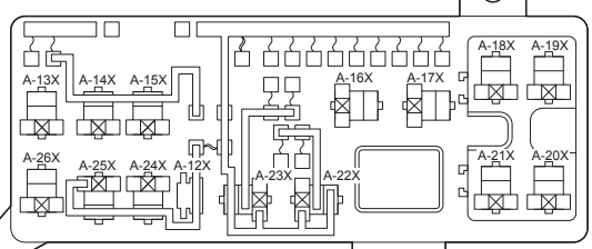
Transcript
| A-12X | Front wiring harness and relay block combination |
| A-13X | Front fog light relay |
| A-14X | Air conditioner condenser fan relay |
| A-15X | Reserve |
| A-16X | Starter relay |
| A-17X | Horn relay |
| A-18X | Heater relay |
| A-19X | Automatic transmission control relay |
| A-20X | Engine control relay |
| A-21X | Air conditioner compressor relay |
| A-22X | Headlight Relay (LO) |
| A-23X | Headlight Relay (HI) |
| A-24X | Power window relay |
| A-25X | Reserve |
| A-26X | Rear fan relay |
In diesel models, an additional heater/heater relay unit is additionally attached.