Mercedes W168 represents the first generation of the A-class of the Mercedes-Benz model range, which was designated A140, A150, A160, A170, A180, A190, A200 and A210 and was produced in 1997, 1998, 1999, 2000, 2001, 2002, 2003, 2004. During this time, the model was restyled. In this publication, you will find information about the location of all electronic control units, a description of fuses and relays Mercedes w168 with block diagrams and photo examples of their implementation. Let’s highlight the cigarette lighter fuse.
The purpose of the fuses and relays may differ from that shown and depends on the year of manufacture and the level of equipment of your car.
Location
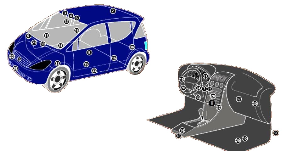
General layout of all electronic control units
Purpose
| 1 | Air conditioning control unit – in the heater control panel |
| 2 | Antenna signal booster |
| 3 | Anti-theft alarm control unit – interior lighting lamps |
| 4 | Vehicle tilt sensor (anti-theft system) – in the anti-theft system control unit |
| 5 | Anti-theft alarm sound signal |
| 6 | Volume change sensors (anti-theft system) – in the anti-theft system control unit |
| 7 | Anti-theft alarm control unit – in the immobilizer control unit |
| 9 | Remote control receiver for additional heater |
| 10 | Battery – Passenger Side Footwell |
| 12 | Clutch actuator control unit |
| 13 | Diagnostic Link Connector (DLC) |
| 14 | Electric window lift control unit – in the front window lift control panel |
| 15 | Left front window lift control unit – in the window lift drive motor |
| 16 | Left rear window lift control unit – in the window lift drive motor |
| 17 | Right front window lift control unit – in the window lift drive motor |
| 18 | Right rear window lift control unit – in the window lift drive motor |
| 19 | Fuse/Relay Box Instrument Panel |
| 20 | Fuse/Relay Box, Footwell |
| 21 | Fuse/Relay Box, Engine Compartment |
| 22 | Sound signals – behind the front bumper |
| 23 | Electronic immobilizer control unit |
| 24 | Ring antenna of the immobilizer – near the ignition switch |
| 26 | Lighting control unit – in the headlight switch |
| 27 | Multifunctional control unit – functions: Central locking, direction indicators, sunroof – in the instrument cluster |
| 28 | Navigation system control unit – in the audio system unit |
| 29 | Ambient air temperature sensor |
| 30 | Parking system control unit |
| 31 | Rain sensor – in the interior rearview mirror |
| 32 | Seat heating control unit – in switch block |
| 33 | Side impact sensor, left |
| 34 | Side impact sensor, right |
| 35 | SRS Electronic Control Unit |
| 36 | Telephone Network Connection Module |
| 37 | Phone Interface Control Unit |
| 39 | Windshield Wiper Intermittent Relay – Windshield Wiper Motor |
Blocks in the cabin
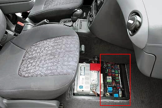
Main block
The main fuse and relay box is located next to the battery, on the front passenger side, under a cover in the footwell. To remove the cover, turn the fastening clips.
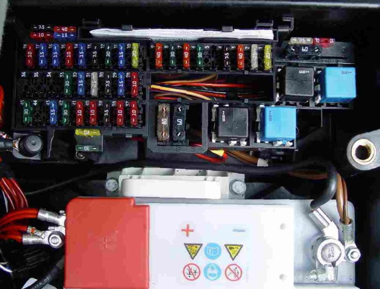
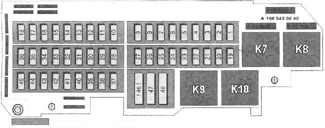
Description
| 1 | 20A Petrol engines: |
| Fuel Tank Ventilation Valve Fan Relay | |
| Fuel injection control unit | |
| Idle speed control unit | |
| EGR valve | |
| Lambda probe heater 1 | |
| Lambda probe heater 2 | |
| Diagnostic connector | |
| Cruise control | |
| Relay boost | |
| Boost Valve (US Models) | |
| Fuel Shut-Off Valve (US Models) | |
| 10A Diesel Engines: | |
| Fan relay | |
| Diesel Engine Power Control Unit | |
| Diaphragm valve | |
| Throttle valve | |
| EGR valve | |
| Catalyst temperature sensor | |
| 2 | 25A Engine Control Unit |
| Ignition coils | |
| Fuel injectors | |
| Fuel pump relay | |
| Electronic accelerator | |
| Starter lock and cut-off relay | |
| 3 | 30A Vehicles without air conditioning: Engine cooling fan |
| 40A Vehicles with air conditioning: Engine cooling fan | |
| 4 | 7.5A Engine Control Unit |
| 5 | 40A Automatic Clutch |
| 6 | 30A Fuel Pump Relay |
| 7 | 40A Car Light Unit |
| 8 | 30A Starter Lock and Cut-off Relay |
| 9 | 40A Wiper Motor |
| 10 | 20/40A Hatch |
| Rear window cleaner | |
| 11 | 15A Cigarette Lighter |
| Steering column switch: | |
| Glass cleaner | |
| Sound signal | |
| Washer pump | |
| Radio navigation system | |
| 12 | 30A Socket in the trunk of the radio |
| Radio | |
| Glove box light | |
| CD changer | |
| 13 | 30A Front door windows |
| 7.5A Power windows for all doors | |
| 14 | 10A Instrument cluster (clock) |
| Windscreen wiper and washer relay | |
| Mobile phone | |
| 15 | 10A Airbag Unit |
| Child seat recognition unit | |
| Side airbag sensor | |
| 16 | 15A Drive for exterior mirrors and mirror heater |
| Parking assistance system | |
| 17 | 15A Sound signal |
| 18 | 10A Instrument cluster |
| Transmitter and receiver of signal from remote control | |
| Electronic Engine Control Unit Relay | |
| Fan relay | |
| 19 | 30A Towing hitch |
| 20 | 15A Towing hitch |
| 21 | 15A Towing hitch |
| 22 | 25A Audio system |
| 23 | 7.5A Mirror Light |
| 24 | Not used |
| 25 | Not used |
| 26 | Not used |
| 27 | Not used |
| 28 | 10A Instrument cluster |
| Window lifters | |
| 29 | 15A Central locking |
| Seat position recognition unit | |
| 30 | 7.5A Transponder and receiver of signal from remote control |
| Electronic instrument panel | |
| 31 | 25A Rear Window Defogger |
| 32 | 15A Mobile phone |
| Radio receiver or radio navigation system | |
| CD changer | |
| Interior lighting | |
| 33 | 30A Window Lifters |
| 34 | 30A Fuel Filter Heater |
| 40A Supercharger (US models) | |
| 35 | 10A Security Alarm Control Unit |
| 2x relays for light and sound signaling | |
| 36 | 25A Heated front seats |
| 37 | 10A Program Switch |
| Coolant Heater Relay | |
| 38 | 10A Air Conditioning Compressor |
| Electric motor of air mixing damper | |
| Cabin air temperature sensor | |
| Washer Jet Heater | |
| 39 | 7.5A Lighting Module |
| Reversing light | |
| 40 | 10A Brake lights |
| 41 | 10A Air Conditioning Compressor |
| Diagnostic connector | |
| 42 | Window lifters |
| 43 | 15A ESP |
| Brake Light Switch Sensor | |
| 44 | 10A Gearbox or Automatic Clutch Control Unit |
| 45 | 30A Interior Heater Fan |
| Air conditioner fan | |
| 46 | 80A On-board network fuse |
| 47 | 60A Power Steering Pump |
| 48 | 60A Diesel Engines: Preheat Control Unit |
| Relay | |
| K7 | Fuel pump relay (002 542 13 19) |
| K8 | Fuel and ignition control unit relay (002 542 25 19) |
| K9 | ESP/VGS or ESP/automatic transmission relay. VGS gearbox control unit (002 542 25 19) |
| K10 | Rear Window Defogger Relay (002 542 13 19) |
Fuses number 11 and 12 are responsible for the operation of the cigarette lighters.
Additional block
Another fuse box is located on the back of the instrument panel, also covered with a protective cover.
Scheme
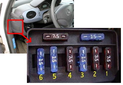
Designation
- 7.5A – Left low beam headlight
- 7.5A – Right low beam headlight
- 15A – High beam, High beam indicator
- 7.5A – Left parking light, Left rear side light
- 15A – Right parking light, Right rear side light, Number plate light, Instrument cluster, terminal 58
- 15A – Fog lights, Rear fog light left
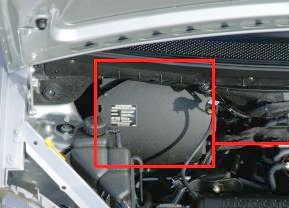
Block under the hood
Under the hood, on the right side of the engine compartment, a block with a relay is installed.
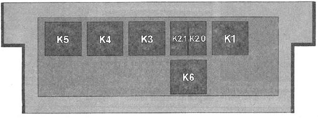
Transcript
| K1 | Washer pump relay |
| K2.0 | horn relay |
| K2.1 | Electronic Stability Program (ESP) relay |
| K3 | starter lock and cut-off relay |
| K4 | radiator fan relay |
| K5 | ESP pump relay |
| K6 | Air Pump Relay (US Models) |