Renault Trafic 3rd generation was produced in 2015, 2016, 2017, 2018, 2019, 2020, 2021, 2022, 2023. In this article, we will present a description of the fuses and relays of Renault Trafic 3 with block diagrams, photographs and their locations. Select the cigarette lighter fuse.

The number of fuses and relays and their number in the blocks may differ from the specified and depends on the year of manufacture and the region of delivery. Check the information with your technical documentation.
Blocks in the cabin
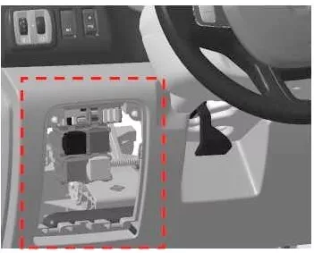
Fuse and relay box
It is located on the left side of the instrument panel behind the storage compartment.
| No. | A | Description |
|---|---|---|
| F1 | 30 | + battery powered rear window wiper |
| F2 | 10 | Main electromagnetic horn |
| F3 | 15 | + accessory socket in the trunk |
| F4 | 30 | + power supply from the battery, driver’s window lift motor time delay |
| F5 | 15 | + power distribution socket for accessories at the rear |
| F6 | 5 | Launch of the high-speed railway + |
| F7 | 15 | + after ignition, seat heating supply |
| F8 | 5 | + EMM battery power (charge power after ignition on VSC) AVS,AUO |
| 15 | + EMM battery power (post-ignition power charge to VSC) SOP03C | |
| F9 | 5 | + general current distribution |
| F10 | 15 | + cigarette lighter socket or front accessory socket, power distribution |
| F11 | 25 | + EMM battery supply (R daytime running lights, forward position, R high beam headlights, L low beam headlights) |
| F12 | 5 | + brake lights with synchronized power supply from the battery, ABS, transponder |
| F13 | 10 | + synchronized power supply from the battery of the interior lighting and air conditioning |
| F14 | 5 | + synchronized power supply from the battery, steering wheel angle Keyless start and stop system |
| F15 | 25 | + After ignition, power supply for rear window wiper, windshield washer pump, horn |
| F16 | 10 | General feed + after ignition |
| F17 | 5 | + after ignition power supply for reverse lights |
| F18 | 5 | + after the ignition switch, the supply stop switch |
| F19 | 5 | + after ignition injection, starter relay, BCM |
| F20 | 5 | + after ignition switch airbag supply, steering column lock |
| F21 | 30 | + after ignition switch supply passenger window switch |
| F22 | 10 | + after ignition, power supply to the power steering pump |
| F23 | 15 | + EMM battery powered brake lights |
| F24 | 15 | + BCM battery power (+ battery power by time) |
| F25 | 10 | + Battery powered BCM, electronic computing units, tire pressure monitoring system and keyless vehicle |
| F26 | 15 | + power from BCM battery for hazard warning lights and turn signals |
| F27 | 25 | + power from BCM battery to lock opening elements |
| F28 | 25 | battery supply + EMM for daytime running lights L, rear position, high beam headlights L, low beam headlights R |
| F29 | 25 | + battery power EMM number plate position, front and rear fog lights |
| F30 | 15 | + battery powered single lever, alarm, sound signal |
| F31 | 5 | + power supply from the dashboard battery |
| F32 | 5 | + single lever battery powered |
| F33 | 20 | + battery socket for towbar |
| F34 | 15 | (supplied with towbar) |
| F35 | 5 | + power switch battery radio, multimedia, mirrors, diagnostic socket |
| F36 | 5 | + heated rear view mirrors |
| F37 | 10 | + electric mirrors with synchronized power supply from the battery, additional UCE adapter unit |
| F38 | 40 | + automatic power switch from the tachograph battery |
| F39 | 40 | + powered by windshield wiper battery |
| F40 | 20 | + relay for distributing power supply current for battery 1 (heating, air conditioning) |
| F41 | 15 | + current distribution equipment pre-equipment additional devices |
| F42 | 10 | + battery powered heater |
| F43 | 10 | + engine feed works additional adaptation |
| F44 | 25 | + supply of heater to the running engine |
| F45 | 25 | + after ignition, power supply to the additional air conditioner unit |
| F46 | 25 | + after ignition switch power relay for keyless car |
| F47 | 20 | Battery powered + EMM for no-load current distribution relay |
| F48 | – | |
| F49 | – | |
| F50 | – | |
| F51 | – | |
| F52 | – | |
| F53 | – | |
| F54 | – | |
| F55 | – |
Fuse number 10 is responsible for the operation of the cigarette lighter.
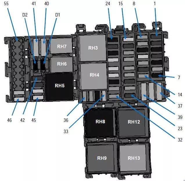
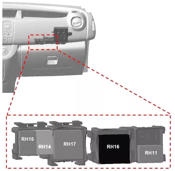
Relay block
It is located on the right side of the instrument panel.
| No. | A | Designation |
|---|---|---|
| RH3 | 40 | Windscreen wiper relay |
| RH4 | 40 | Windscreen wiper 2nd speed relay |
| RH5 | 40 | + after the ignition switch, power supply for the rear passenger compartment heating and air conditioning relay |
| RH6 | 20 | Matrix Heater Water Pump Relay Support |
| RH7 | 20 | Driver’s Door Lock Relay (SDO) |
| RH8 | 70 | + current distribution relay No. 1 |
| RH9 | 40 | + current distribution relay No. 2 |
| RH11 | 20 | Electric window relay |
| RH12 | 40 | Mirrors + rear window heating relay |
| RH13 | 40 | Rear Window Wiper Relay |
| RH14 | 20 | Central door lock relay |
| RH15 | 20 | Electric window relay |
| RH16 | 40 | After ignition switch No. power relay. 2 (cars with hands-free card) |
| RH17 | 40 | Engine running + relay |
| RH18 | – | |
| RH19 | – | |
| RH20 | – |
Blocks under the hood
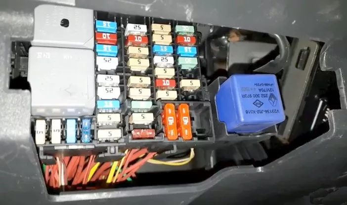
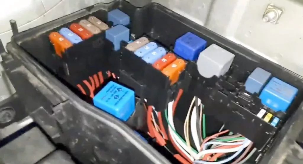
Fuse and relay box
This fuse and relay box is located on the left side, next to the battery.
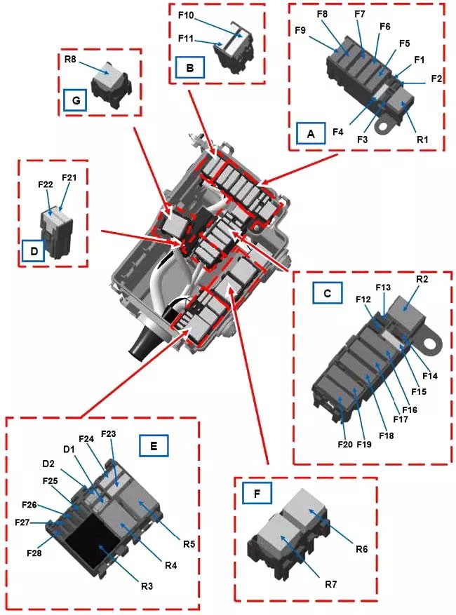
| No. | A | Purpose |
|---|---|---|
| F1 | – | – |
| F2 | – | – |
| F3 | 25 | ABS/ESP |
| F4 | 30 | Starter |
| F5 | 70 | Passenger cabin 1 |
| F6 | 70 | Passenger cabin 3 |
| F7 | 50 | ABS/ESP |
| F8 | 60 | Passenger cabin 2 |
| F9 | 20 | Heated mirrors |
| 40 | Rear window + heated mirrors | |
| F10 | – | – |
| F11 | – | – |
| F12 | – | – |
| F13 | – | – |
| F14 | 15 | Air conditioning compressor |
| F15 | 15 | Fuel pump |
| F16 | 70 | Heater control unit |
| F17 | 60 | Heating element block |
| F18 | 60 | Heating element block |
| F19 | 40 | Engine index *408 and air conditioning or 450 and heating Electric fan assembly 1 |
| 50 | Engine index *408 and heating or 450 and air conditioning Electric fan assembly 1 | |
| F20 | 40 | Engine Suffix *408 and Air Conditioner or 450 Electric Fan Assembly 2 |
| F21 | – | – |
| F22 | – | – |
| F23 | – | – |
| F24 | – | – |
| F25 | – | – |
| F26 | 25 | Diesel heater |
| F27 | 20 | Engine injection system |
| F28 | 15 | Engine injection system |
| Relay | ||
| R1 | 20 | Starter |
| R2 | 20 | Fuel pump relay |
| R3 | 40 | Injection power relay |
| R4 | 20 | Compressor control relay |
| R5 | – | – |
| R6 | 70 | High Speed (Electric Fan Unit 1) |
| R7 | 40 | Low speed (electric fan) |
| R8 | 40 | High Speed (Electric Fan Unit 2) |
| Diodes | ||
| D1 | Air conditioning compressor | |
| D2 | – | |
Power block
A high-power fuse block is attached to the positive terminal of the battery.
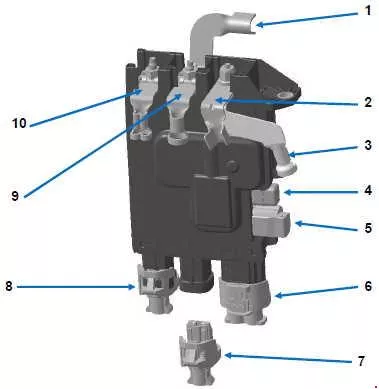
| No. | A | Purpose |
|---|---|---|
| 1 | Battery protection power supply wiring | |
| 2 | 300 | Engine Wiring (Generator) |
| 3 | 300 | Engine wiring (starter) |
| 4 | 5 | Mini Fuse with Cap (Start/Stop) |
| 5 | 5 | Cabin Wiring (Start/Stop) |
| 6 | 50 | Cabin wiring (options for converting KPD and KS6 or trailer towbar) |
| 7 | Reserved for conversion by body builders. | |
| 8 | 35 | Engine Wiring (Engine Management) |
| 9 | Engine connection block | |
| 10 | 120 | Cabin Wiring (Power Steering) |