Volvo FH 12 represents the 1st generation of the family of heavy-duty trucks, which was produced in 1994, 1995, 1996, 1997, 1998, 1999, 2000, 2001, 2002, 2003 and 2004. During this time, the model was restyled. In our material, you will find a description of the fuses and relays of the Volvo FH 12 with block diagrams, photographs and their locations. We will highlight the fuse responsible for the cigarette lighter. This material will also be useful to owners of the Volvo FH 16.

The purpose of the fuses and relays may differ from the one shown and depends on the year of manufacture, modification and level of electrical equipment of your car. Check the information with your diagrams on the block cover.
Blocks in the cabin
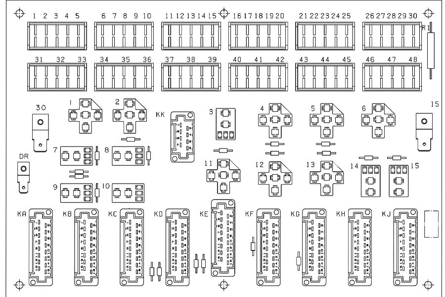
Block layout diagram
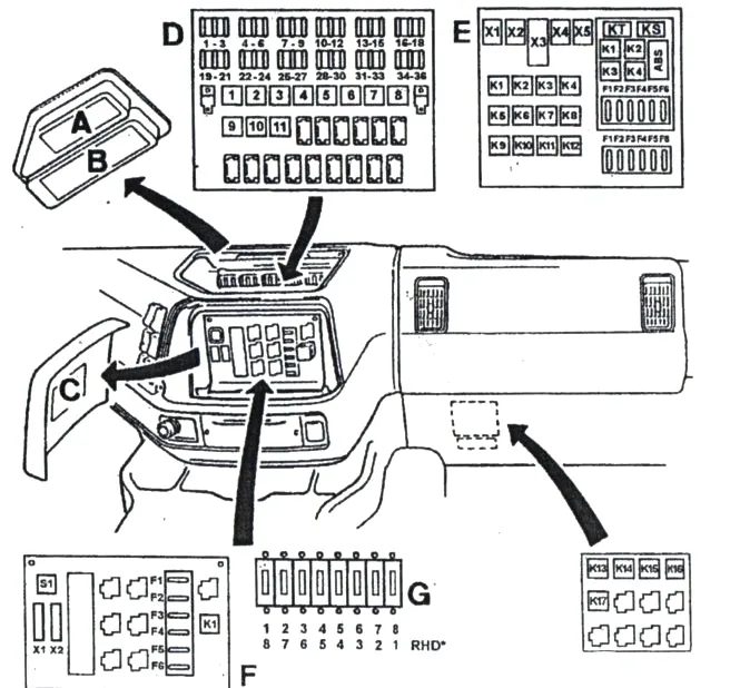
Block D
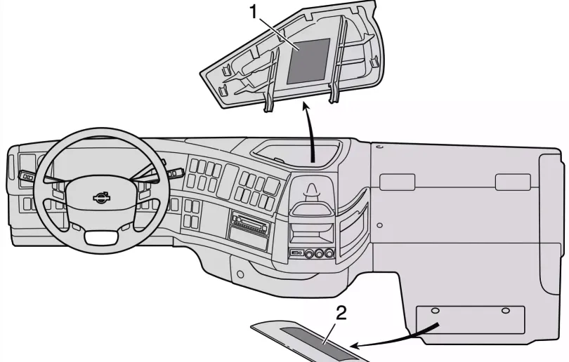
To gain access, you need to remove the protective cover.
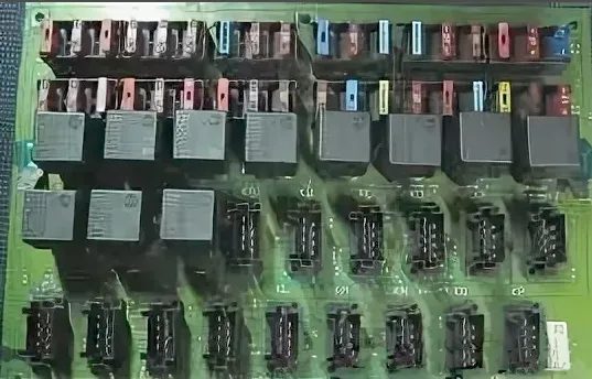
The block itself will look something like this.
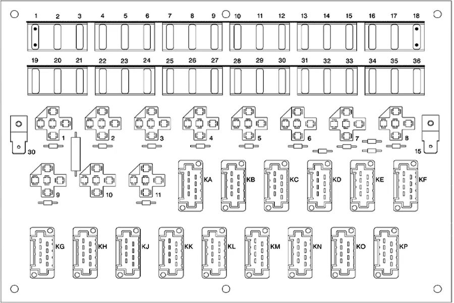
- F1 – low beam headlights left
- F2 – low beam headlights right
- F3 – independent heater, webasto, radio
- F4 – brake, stop lights, stop light fuse
- F5 – reversing lights, generator charging lamp, generator excitation, reverse fuse
- F6 – interior lighting, radio, central locking fuse, interior lighting and sockets
- F7 – emergency signaling
- F8 – turns, signal lights
- F9 – tachograph, clock, hazard warning lights, lighting, fuse, instruments and tachograph
- F10 – air conditioner, indoor heating fan motor
- F11 – Automatic transmission, transmission, gearbox control unit fuse
- F12 – windshield wiper and washer motor, windshield wiper and washer
- F13 – headlight washers, headlight wiper fuse
- F14 – spotlight, additional headlights, spotlight fuse
- F15 – Engine preheating – glow plugs, glow plug heater fuse
- F16 – cigarette lighter , converter
- F17 – front fog lights, rear fog lights fuse
- F18 – EDC engine control unit
- F19 – high beam, left side, fuse on the left headlight wiring diagram
- F20 – high beam right side, fuse on the right headlight circuit diagram
- F21 – 24 volt sockets, bedside lamp, interior lighting fuse
- F22 – reserve
- F23 – air suspension, frame lift
- F24 – dimensions left side
- F25 – spotlight
- F26 – trailer parking light left side, fuse on parking light wiring diagram
- F27 – air conditioner
- F28 – dimensions right side
- F29 – EDC engine control unit
- F30 – trailer parking light right side
- F31 – differential lock, power take-off mechanism
- F32 – sound signal, additional equipment
- F33 – driver’s side window lift
- F34 – central locking, window lift on the passenger side
- F35 – low beam
- F36 – mirror heating
Relay
- 302 – Lighting relay (additional spotlight)
- 305 – Reverse light relay
- 306 – Low beam headlight relay
- 307 – High beam headlight relay
- 308 – Brake light lamps brake light relay
- 309 – Dimensions relay
- 315 – Starter relay
- 343 – Rear fog light relay
- 375 – Daytime running light relay, Generator
Option 2
Scheme
- F1 Air suspension, hydraulic trolley lift
- F2 Area inhibitors, compressor control
- F3 Airbag, immobilizer
- F4 Central locking
- F5 Interior lighting, timer
- F6 Trailer stops
- F7 Devices
- F8 Voltage divider for radio
- F9 Feet
- F10 Spotlight
- F11 High beam blink
- F12 Air suspension
- F13 Electrically heated rear view mirrors
- F14 Heating of relay “radiopos”
- F15 Low beam LHS
- F16 High beam LHS
- F17 “Radiopos”
- F18 Cooling fan control, heating relay
- F19 Car ECU
- F20 Solenoid valves engine
- F21 Instruments, el. with heating mirror relay
- F22 Daylight
- F23 Dryer heating
- F24 Additional equipment
- F25 Electric rear view mirrors
- F26 Differential lock, power take-off
- F27 Electronic climate control
- F28 Direction indicator, instruments
- F29 Horn
- F30 Cigarette lighter
- F31 Voltage divider 12V
- F32 Rear fog lights
- F33 Left side light
- F44 Trailer side light left
- F55 Luggage compartment lighting
- F56 Side light right trailer
- F57 Right side light
- F58 Direction indicator, hazard warning
- F59 Near Right
- F30 High beam right
- F31 Electric window, passenger side
- F32 Electric window, driver side
- F33 Engine ECU
- F34 Reverse light, reverse warning, alarm
- F35 Fan, climate control unit
- F36 El heated seat, park. heater
- F37 Windscreen wiper
- F38 Windscreen wiper and headlamp washer
Relay
- 301 Relay, fog lights “9” (CG5)
- 305 Relay, reverse lights “12” (EA7)
- 306 Relays, full beams “11” (CE55)
- 307 Relay, low beam “3” (CE48)
- 308 Relay, brake lights truck “8” (CK8)
- 308V Relay, brake lights trailer “10” (CK15)
- 309L Relay, left side lights “1” (CE19)
- 309R Relay, right side lights “2” (CE26)
- 315R Relay, starting switch “4” (AA42)
- 343 relay, rear fog lights “7” (CG12)
- 348A Relay, fan, climate control unit “13” (HA 6)
- 360 Relay, power take-off inhibitor “14” (LD3) (LE4)
- 379 Relay, fuel injection “5” (AC17)
- 3005 Generator controlled relay “6” (AA52)
- 3101 Relay, internal lamps “15” (ER13) (ES13)
Block E
Connectors
- X1 – Free
- X2 – Automatic transmission “AG2”
- XZ – Automatic transmission “AGS1”
- X4 – Air suspension “BL”
- X5 – Anti-lock system “AS”
Fuses
- P1 – Additional heater (20A)
- P2 – Additional heater (15A)
- RZ – Free
- P4 – Free
- P5 – Electric seat heating (15A)
- P6 – Electrical input 12V (15A)
Fuses
- P1 – Electrovalve, anti-lock system
- P2 – Electrovalve, anti-lock system
- RZ – Relay, control unit (5A)
- P4 – Information block (5A)
- P5 – Diagnostic input (5A)
- P6 – Trailer power supply (25A)
- K1 – Spotlights “302”
- K2 – Air suspension, level adjustment ««3014A»
- KZ – Air suspension, level adjustment “3014B”
- K4 – Air suspension “3014S”
- K5 – Seat adjustment “3076”
- Kb – Electrically heated rear view mirrors
- K7 – Air suspension, bogie lift “314D”
- K8 – Air suspension, strut lift “314E”
- K9 – Automatic transmission, EES. engine braking ADR “345B” “318A” “309AB”
- K10 – Automatic transmission, EES, engine braking ADR “3073” “318B” “309AL”
Anti-lock braking system fuses
- K1 – Electrovalve, anti-lock braking system
- K2 – Brake lights, trailer
- KZ – Electrovalve, anti-lock braking system
- K4 – Indicators, anti-lock braking system
Block H
Additional equipment block (optional). Located on the bottom right of the diagram. Here may be located the protection elements: Air conditioner, Control unit, Parking heater (water), etc.
Block G
Electronic blocks
- Multifunctional relay
- EDC System
- Lighting relay
- Centralized blocking
- Column lift, A-type
- Strut lift (ATV), stroke (A-type, pneumatic)
- Strut lift (ATV). A-type
- Dim-Dip (UK)
Block F
- S1 – Diagnostic device key
- X1 – Engine control unit, driver information system
- X2 – Anti-lock braking system
Body electrical circuit
Fuses
- F1 – Battery -30
- F2 – Battery -30
- F3 – Start switch “15”
- F4 – Start switch “15”
- F5 – Alternator “61” (5A)
- F6 – Parking lights (5A)
Relay
- K1 – Power supply via fuses 3 and 4
A high-power fuse box may also be installed next to the battery.

A high-power fuse box may also be installed next to the battery.
- 125A Pre-heating
- 200A Hydraulic Bogie Lift / Body Manufacturer
- 125A Cabin
- 40A Secondary Power Supply for Flashlights