The five-door subcompact Kia Venga was introduced in 2009. It was produced in 2010, 2011, 2012, 2013, 2014, 2015, 2016 and 2017 with gasoline and diesel engines. During this period, the model was restyling once. In our article you will find a description of the fuses and relays of the Kia Venga with block diagrams, their locations and photos. We will show the fuse of the Kia Venga cigarette lighter.
Cabin block
Located under the instrument panel on the driver’s side. Remove the cover to access.
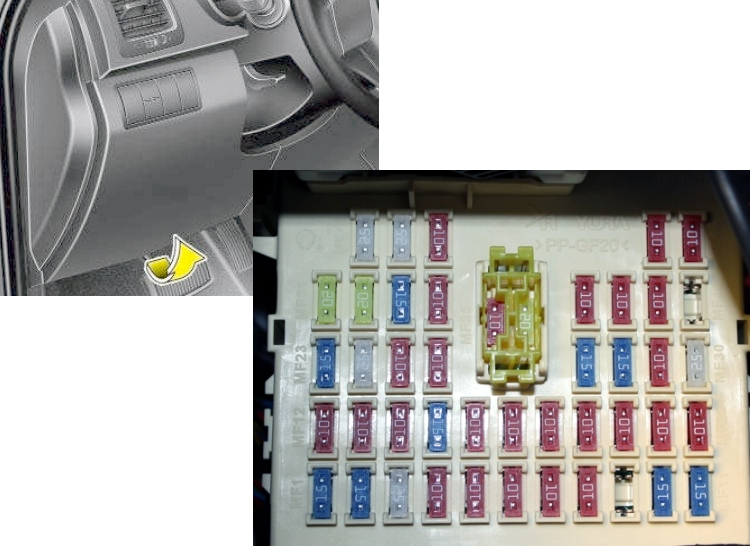
Example of an original circuit from the cover
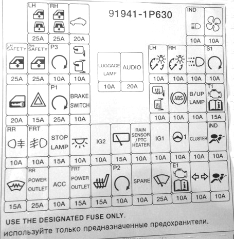
Description
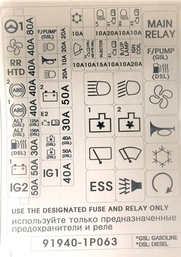
| POWER WINDOW | 25A Left electric door lift |
| POWER WINDOW | 25A Right electric door lift |
| OUTSIDE MIRROR HEATED | 10A Heated exterior mirrors |
| BLOWER | 10A Air conditioning system, ECU |
| DOOR LOCK | 20A Door lock/unlock |
| SUNROOF | 20A Roof hatch |
| SAFETY POWER WINDOW | 15A Safety glass servo (driver) |
| FOLDING MIRROR | 10A Exterior mirror folding switch, center switch |
| TAIL LAMP | 10A Left tail light |
| TAIL LAMP | 10A Right rear light |
| START | 10A Engine start relay |
| HAZARD WARNING SIGNAL | 15A Emergency alarm |
| POWER DISTR-ON MODULE | 25A PDM control module |
| MOTOR DRIVER POWER | 10A EUR |
| STOP SWITCH | 10A Brake light switch |
| TRANS-ON CONTROL UNIT | 15A Speed sensor |
| IGNITION COIL | 15A Ignition coil, capacitor |
| IGNITION | 10A Power – HLLD Switch, BCM, Air Conditioning System, Sunroof |
| WINDSCREEN WIPING | 25A Front wiper motor relay, multi-function wiper switch |
| FRONT FOG LAMP | 10A Front fog lamp, BCM |
| REAR FOG LAMP | 10A Rear fog lamp, BCM |
| ROOM LAMP | 10A Interior light switch |
| STOP LAMP | 15A Stop switch, BCM |
| CLUSTER | 10A Cluster, BCM, Clock |
| IGNITION | 10A Power supply for audio, TPMS, alarm system |
| ANTI-LOCK BRAKE SYSTEM | 10A Speed sensor, ABS (ESP), ESP Switch |
| RAIN SENSOR (PTC HEATER) | 10A Rain sensor relay (PTC, fuel filter heater) |
| POWER DISTRIBUTION | 10A Smart Key Block, SSB |
| FRONT HEAT RAYS | 15A Windshield heater |
| POWER OUTLET | 15A Front cigarette lighter socket |
| POWER OUTLET | 25A Rear socket, center socket |
| IGNITION | 10A Power – Audio, digital clock |
| AIR BAG INDICATOR | 10A Cluster (airbag indicator) |
| AIR BAG | 10A Airbags |
| TURN SIGNAL LAMP | 10A Multifunction Light Switch |
| WIPER SYSTEM RR | 15A Rear wiper motor, rain sensor, multi-function wiper switch |
| SEAT HEATER | 15A Seat heating |
| AUDIO | 20A Audio |
| LUGGAGE LP | 10A Luggage compartment lamp |
The cigarette lighter and additional socket fuse will be marked as POWER OUTLET on the diagram.
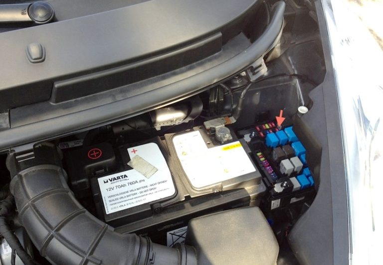
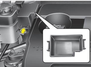
Block under the hood
Main unit
Located in the left side of the engine compartment under the protective cover.
Appointment
| OJSC 1 | 50A Dashboard junction box (trunk relay, fuse (F12 10 A, F13 10 A, F14 10 A, F15 15 A, Power connector (F35 10 A, F36 20 A)), interior 10 A, audio system 20 A |
| OJSC 2 | 50A Junction box l/P (HAZARD 15A, relay – window lifter, fuse -P/WDW LH 25A, P/WDW RH 25A, SAFETY P/WDW 15A) |
| C/FAN | 40A Fan relay (high speed), fan relay (low speed) |
| ALL | 125/150A Diesel fuse and relay box (SPLUG 80 A, PTC 1, 2, 3, 50 A), generator Engine compartment relay and fuse block (F1 80 A, F2 40 A, F3 40 A, F4 40 A, F5 4 A, F18 10 A) |
| ABS2 | 40А ABS, ESP |
| ABS 1 | 40А ABS,ESP |
| RR HTD | 40A Junction box l/P (Rear heater relay) |
| BLOWER | 40A Fan motor |
| MDPS | 80A Power steering control |
| IG2 | 40A Ignition switch, PDM relay block, engine compartment relay and fuse block (relay 6) Instrument panel junction box F8 50 A (trunk relay, fuse (F12 10 A, F13 10 A, F14 10 A, F15) |
| ECU 1 | 20А ECU |
| F/PUMP | 20A Fuel Pump Relay (Gasoline) |
| IG1 | 40A Ignition key (Electrical equipment) |
| H/LP | 20A Headlight low beam |
| H/LP LO LH | 10A Left headlight low beam |
| H/LP LO RH | 10A Right headlight low beam |
| H/LP HI | 20A High beam headlight |
| HORN | 10A Horn, anti-theft alarm, battery sensor |
| ECU 4 | 10A ECU (Gasoline) |
| FUEL HTR | 30A Fuel filter heater (diesel) |
| A/CON 1 | 10A Air conditioning relay |
| A/CON 2 | 10A Air conditioning system |
| ECU3 | 10A Immobilizer, brake light switch, IMV, MPROP |
| ECU 2 | 30A ECU 4 10A, Main relay, fuse – ECU 1 20A, ECU 3 10A, SENSOR 10A. INJECTOR 15A |
| DRL | 10A Daylight bulb |
| SENSOR | 10A Petrol – air conditioning relay, cooling fan relay (high speed, low speed), camshaft position sensor, immobilizer, petrol vapor tank purge solenoid valve, oxygen sensor (high/low)< ai=1> Diesel – air conditioning relay, cooling fan relay (high speed, low speed), lambda sensor |
| INJECTOR | 15A Gasoline – Injector No. 1 -4, fuel pump relay, oil control valve Diesel – EGR system electric starter, immobilizer, VGT actuator, crankshaft position sensor, spark plug relay, PTC HTR 1 relay |
Additional unit
Installed on models with a diesel engine.
Here are the elements responsible for the operation of the engine.
Marking
| GLOW | 80A Glow plugs, air heater relay |
| PTC HTR 1 | 50A RTS heater 1 |
| PTC HTR 2 | 50A RTS heater 2 |
| PTC HTR 3 | 50A RTS heater 3 |
Check the assignment of fuses and relays with your diagrams on the back of the protective cover.