Kia Rio 2nd generation was introduced at the end of 2005. It was produced in 2006, 2007, 2008, 2009, 2010, 2011. During this period, RIO 2 underwent restyling. In our material you will find information with a description of fuses and relays of Kia Rio 2nd generation with block diagrams and their locations. We note the cigarette lighter fuse.

The design of the blocks and the number of elements in them may vary. Check with your diagrams on the protective cover.
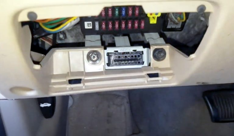
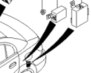
Cabin block
It is located under the panel on the driver’s side, behind a protective cover, where the diagnostic connector is also located.
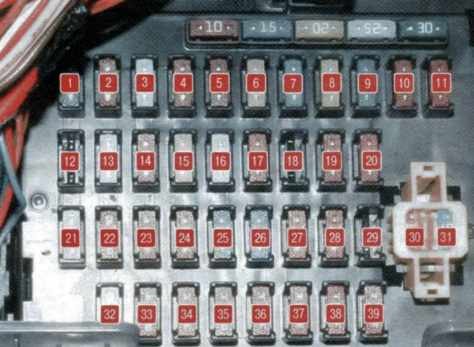
Fuse description
| 1 | 15A RR WIPER Tailgate wiper |
| 2 | 10A H/LP Left headlight bulb |
| 3 | 25A FR WIPER Windshield wiper |
| 4 | 10A BLOWER Fan |
| 5 | 10A H/LP (RH) Right headlight bulbs |
| 6 | 20A S/ROOF Roof hatch |
| 7 | 15A STOP LP Stop signals |
| 8 | 20A C/DR LOCK Central door lock switch |
| 9 | 15A IGN COIL Ignition coil |
| 10 | 10A ABS Anti-lock braking system |
| 11 | 10A B/UPLP Reverse light lamp |
| 12 | BMS – Reserve |
| 13 | 25A C/LIGHTER Cigarette lighter |
| 14 | 10A FOLD’G Drive for folding exterior rear-view mirrors |
| 15 | 20A HTR SEAT Seat heating |
| 16 | 25A AMP Amplifier |
| 17 | 10A FR FOG LP Fog lights |
| 18 | 10A DRL Daytime Running Lights |
| 19 | 10A ECU Engine Control System |
| 20 | 10A CLUSTER Instrument panel |
| 21 | 25A P/WDW RH Power window lock (right side) |
| 22 | 10A AUDIO Audio system, trip computer |
| 23 | 10A RR FOG LP Rear fog lamp |
| 24 | 10A IGN Switch (Ignition Switch) |
| 25 | 30A HTD GLASS Rear window heating |
| 26 | 15A A/BAG Airbag |
| 27 | 10A TCU Automatic Transmission Control Unit |
| 28 | 10A SNSR Sensors |
| 29 | SPARE – Reserve |
| 30 | 10A MULT B/UP Air conditioning control unit, clock, interior lighting ceiling ETACS |
| 31 | 15A AUDIO Audio system |
| 32 | 25A P/WDW LH Power window lock (left side) |
| 33 | 10A HTD MIRR Heated exterior rear-view mirror system |
| 34 | 10A TAIL LP(LH) Left rear position light |
| 35 | 10A TAIL LP(RH) Right rear position light |
| 36 | 10A HAZARD Alarm |
| 37 | 10A T/SIG LP Turn signal lights |
| 38 | 10A A/BAG IND Airbag warning light |
| 39 | 10A START Red Starter relay |
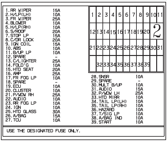
The cigarette lighter fuse is marked on the diagram as number 13 at 25A.
On the back of the unit are some relay elements: hazard warning and turn signal relays, horn relays, etc.
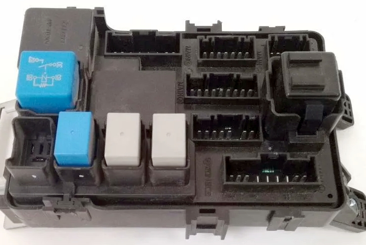
In sedans, a separate brake light relay is located in the rear, next to the rear light control unit.
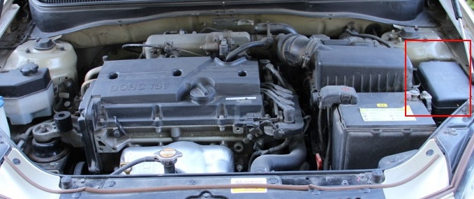
Blocks under the hood
Main unit
Located in the left side of the engine compartment.
Example of a diagram on the back of the protective cover
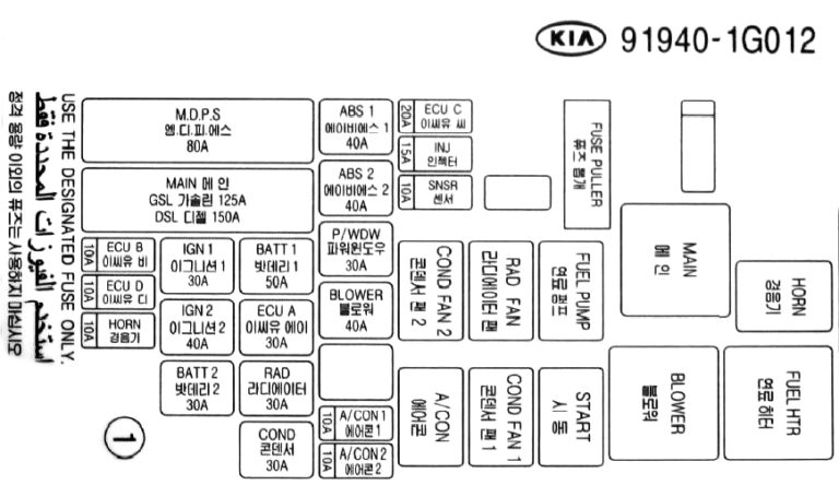
Photo – diagram
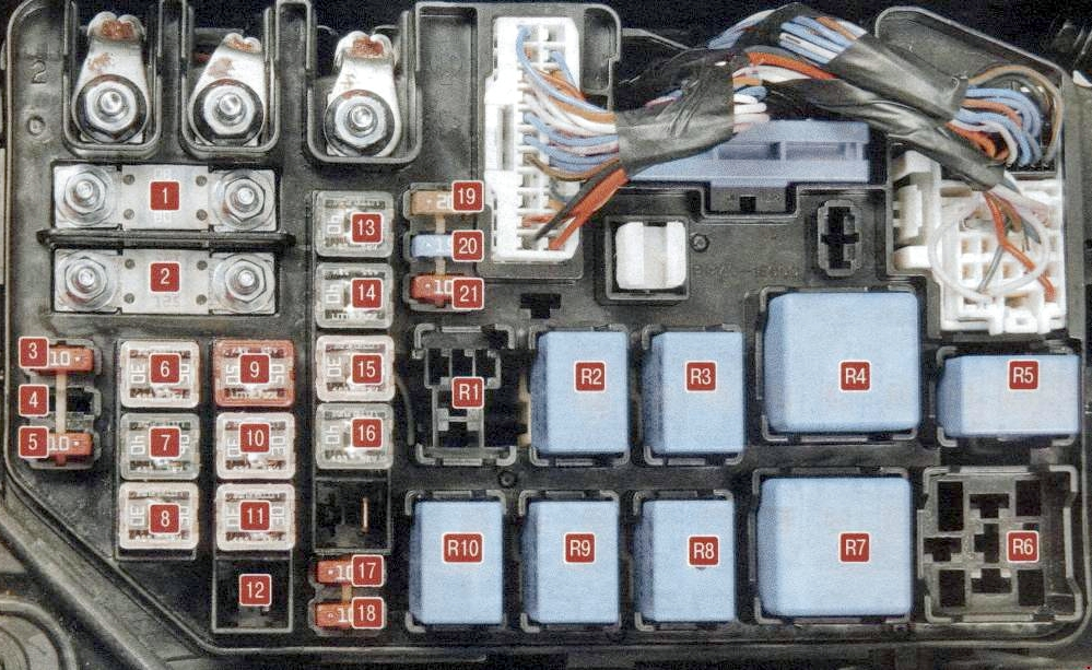
Fuse designations
| 1 | 80A MDPS Electric power steering |
| 2 | 125/150A MIN Generator |
| 3 | 10A ECUB Engine control unit |
| 4 | 10A ECUD Engine control unit |
| 5 | 10A HORN Sound signal |
| 6 | 30A IGN1 Ignition switch (lock) |
| 7 | 40A IGN2 Starter, ignition switch (lock) |
| 8 | 30A BATT2 Alternator, battery |
| 9 | 50A BATT1 Alternator, battery |
| 10 | 30A ECUA Engine control unit |
| 11 | 30A RAD Electric radiator fan |
| 12 | 30A COND Condenser fan |
| 13 | 40A ABS1 ESP stability control system and ABS anti-lock braking system |
| 14 | 40A ABS2 ESP stability control system and ABS anti-lock braking system |
| 15 | 30A P/WDW Electric window lifts |
| 16 | 40A BLOWER Radiator fan relay |
| 17 | 10A A/CON 1 Air conditioner |
| 18 | 10A A/CON 2 Air conditioner |
| 19 | 20A ECUC Engine control unit |
| 20 | 15A INJ Fuel injectors, air conditioning system |
| 21 | 10A SNSR Sensors |
Relay purpose
| R1 | COND FAN 2 Condenser electric fan relay (low speed) |
| R2 | RADFAN Radiator fan relay |
| R3 | FUEL PUMP Fuel pump relay |
| R4 | MAIN Main relay |
| R5 | HORN Horn relay |
| R6 | FUEL HTR Fuel filter heater relay |
| R7 | BLOWER Heater fan motor relay |
| R8 | START Starter relay |
| R9 | COND FAN 1 Condenser electric fan relay (high speed) |
| R10 | A/CON Air conditioning relay |
Additional unit
Installed in models with diesel engines.
Scheme
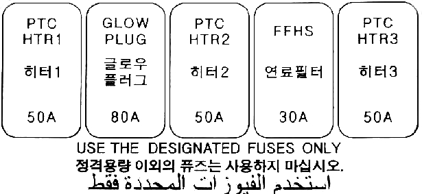
Transcript
| PTC HTR 1 | 50A RTS Heater |
| GLOW PLUG | 80A Glow plug |
| PTC HTR 2 | 50A RTS Heater |
| FFHS | 30A Fuel filter heating |
| PTC HTR 3 | 50A RTS Heater |