The Volvo VN truck tractor
has been produced since 1996 with various modifications and changes, designated as
VNL , VNM, VHD, etc. In our article, we will present a description of the Volvo VNL fuses and relays with a block diagram and its location. Note the cigarette lighter fuse.
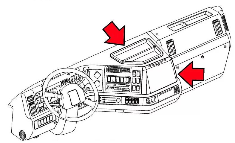
Fuse and relay box
All Volvo VN models have a common location of the main fuse and relay unit, in the central part of the panel. To access it, you need to remove the protective cover.
The block itself will look something like this:

Check the assignment of fuses and relays with your diagram located on the back of the protective cover or other technical documentation.


| No. | Description of fuses |
|---|---|
| 1 | control unit on the driver’s door (locks, windows, mirrors) |
| 2 | radio, cd, amplifier |
| 3 | Driver’s window lift and heated mirror |
| 4 | passenger window lift |
| 5 | steering column control module |
| 6 | additional equipment (accessory expansion) |
| 7 | not used |
| 8 | Power Supply #1 Light Control Module (LCM) |
| 9 | trailer lighting, trailer marker relay |
| 10 | Power Supply #2 Light Control Module (LCM) |
| 11 | Battery/Volvo Link |
| 12 | road relay/battery |
| 13 | diagnostic connector |
| 14 | qualcom |
| 15 | ignition key terminal “B” |
| 16 | ignition key terminal “30” |
| 17 | Power Supply #3 Light Control Module (LCM) |
| 18 | trailer parking relay |
| 19 | backlight in battery compartment |
| 20 | Battery discharge protection module |
| 21 | Cummins Engine DR |
| 22 | fuel filter |
| 23 | climate control backlight |
| 24 | instrument panel |
| 25 | heated seats |
| 26 | wipers |
| 27 | differential lock |
| 28 | wheel lock |
| 29 | camera preparation / Body Builder Ignition Z |
| 30 | electric driver’s seat |
| 31 | Electric passenger seat |
| 32 | ignition expansion |
| 33 | Snowplow Lights LH |
| 34 | central tire inflation |
| 35 | RH Snow Plow Lights |
| 36 | cigarette lighter |
| 37 | cabin lighting |
| 38 | – |
| 39 | radio station |
| 40 | suspension (ECS) |
| 41 | air horn |
| 42 | Power Supply #5 Light Control Module (LCM) |
| 43 | trailer stops, relay |
| 44 | Power Supply #6 Light Control Module (LCM) |
| 45 | electric sound signal |
| 46 | constant (non-switchable) power supply for radio and devices |
| 47 | Main power supply for heater/air conditioner fan |
| 48 | central locking |
| 49 | AUX1 |
| 50 | AUX2 |
| 51 | AUX3 |
| 52 | Battery discharge protection module |
| 53 | additional 12 volt socket |
| 54 | additional non-switchable power supply |
| 55 | – |
| 56 | air dryer, brakes |
| 57 | airbag (SRS) |
| 58 | lifting axles / body reverser |
| 59 | qualcomm / Inside/Outside Air |
| 60 | road relay / body builder Ign-Y/Ing. Exp. |
| 61 | ABS |
| 62 | ABS |
| 63 | suspension |
| 64 | fifth wheel lock |
| 65 | Light Control Module (LCM) |
| 66 | body builder Ign-X |
| 67 | coolant pump VED16 |
| 68 | central locking |
| 69 | additional nutrition |
| 70 | Vorad/ECS |
| 71 | not used |
| 72 | ignition for the box – automatic |
| 73 | ICON only with Cummins |
| 74 | radio with icon/amplifier |
| 75 | PTO power take-off box |
| 76 | Jake Brake, Engine Brake, Exhaust Brake |
| 77 | Allison D.R. |
| 78 | Allison Battery |
| 79 | EMS A |
| 80 | EMS B/ Deairation Sw |
| 81 | EMS System/VECU |
| 82 | Body Builder module |
| 90 | Fuel pump |
| 91 | |
| 92 | Indoor lamps |
Fuse number 36 is responsible for the operation of the cigarette lighter.
| No. | Relay designation |
|---|---|
| 1 | RELAY.DR |
| 2 | RELAY. TRAILER PARKING |
| 3 | RELAY. TRAILER-STOP |
| 4 | RELAY. EMS |
| 5 | RELAY. LIFT AXLE / REVERSE SIGNAL |
| 5A | RELAY. Temp. Start DR |
| 6A | RELAY. Temp. Start IGN |
| 7 | RELAY. PTO |
| 9 | RELAY TRAILER MARKER |
| 10 | RELAY. CITY SIGNAL |
| 11 | RELAY. Interior lighting / DOOR LIGHTS |
| 12 | RELAY. INTERMITTENT WIPER |
| 13 | RELAY. AUTO-BIAS |
| 13_1 | RELAY. ALLISON START ON |
| 14 | RELAY. ALLISON AUTO-NEUTRAL |
| 14_1 | RELAY. Parking brake TAS |
| 15 | RELAY. ALLISON POWER |
| 16 | RELAY. BODY BUILDER REMOTE THROTTLE INC. |
| 17 | RELAY. BODY BUILDER REMOTE THROTTLE DEC. |
| 18 | RELAY. ALLISON SERVICE BRAKE INPUT |
| 20 | RELAY. ALLISON BODY BUILDER1 |
| 21 | RELAY. ALLISON BODY BUILDER2 |
| 26 | SNOW MACHINE LH ER8 |
| 27 | SNOW PLAW RH ER9 |
| 28 | SNOW ENTRY LCM INPUTER7 |
| 29 | POWER RELAY 1 BATTERY |
| 30 | POWER RELAY 2 IGNITION |
| 31 | POWER RELAY 3 IGNITION |
| 32 | POWER RELAY 4 ACCESSORIES |
| 33 | Relay. ER9 Motorized Mirror IN |
| 33A | Relay. ER8 Motorized Mirror OUTPUT |
| 34 | ER8 ECS Rower |
| 35 | MEIR ER3 |
| 36 | Relay. ER7 Electric window lifter “UP” |
| 37 | Relay. ER6 Electric window lifter “DOWN” |
| 38 | Roof marker lights ER2 |
| 39 | Sleeper HVAC Relay on Wiring Harness |
| 40 | RELAY STARTER ENGINE |
| 41 | RELAY. PARKING BRAKE |
| 42 | ENGINE WARM-UP RELAY |
| 43 | Relay, Shunt |
| 44 | Battery Protection Relay ER8 |