Toyota Yaris 2 generation was produced in 2005, 2006, 2007, 2008, 2009, 2010, 2011, 2012 and was designated as P90. During this time, the model was restyled. This car was supplied all over the world. In some countries it is also known as Toyota Vitz / Toyota Belta . A distinctive feature of the models is the side of the steering wheel. In this publication you can find a description of the location of electronic control units, the purpose of fuses and relays Toyota Yaris / Vitz / Belta 2 with block diagrams and photo examples of their implementation. Note the cigarette lighter fuse.

Blocks in the cabin
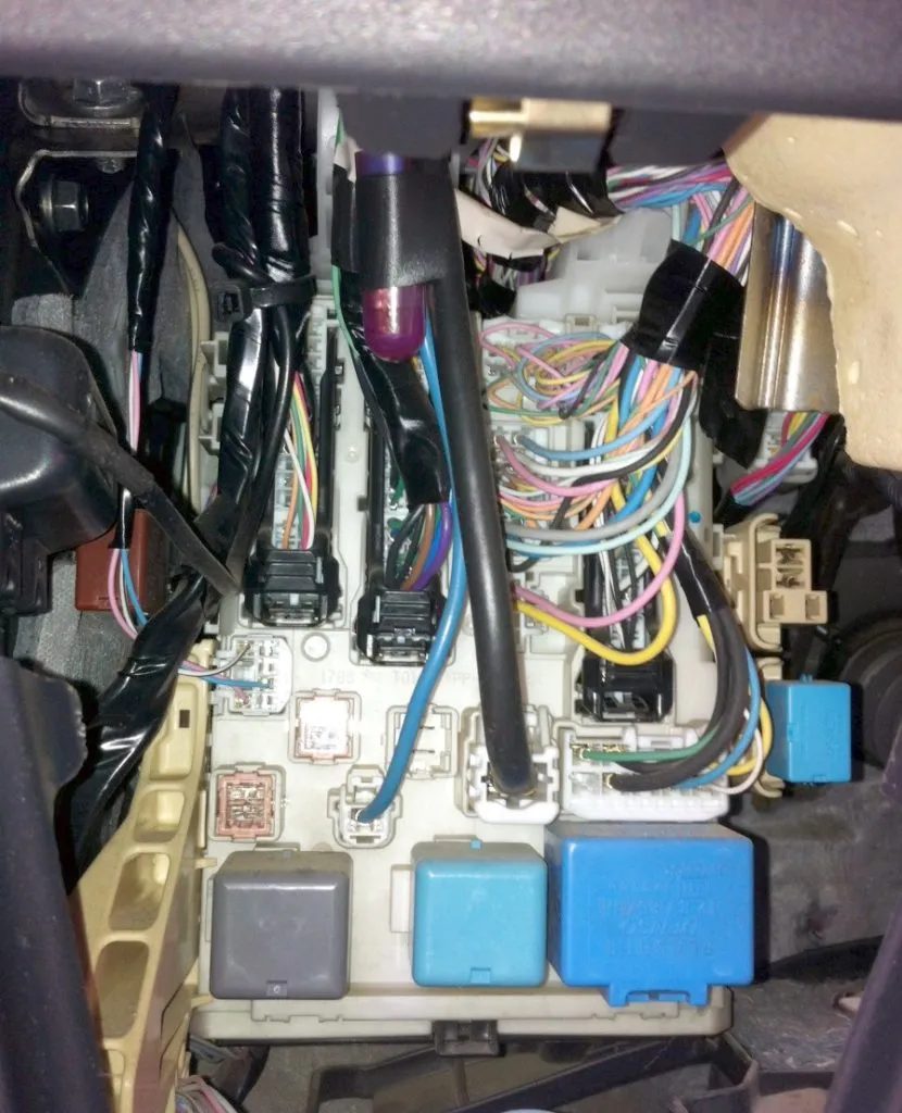
Location
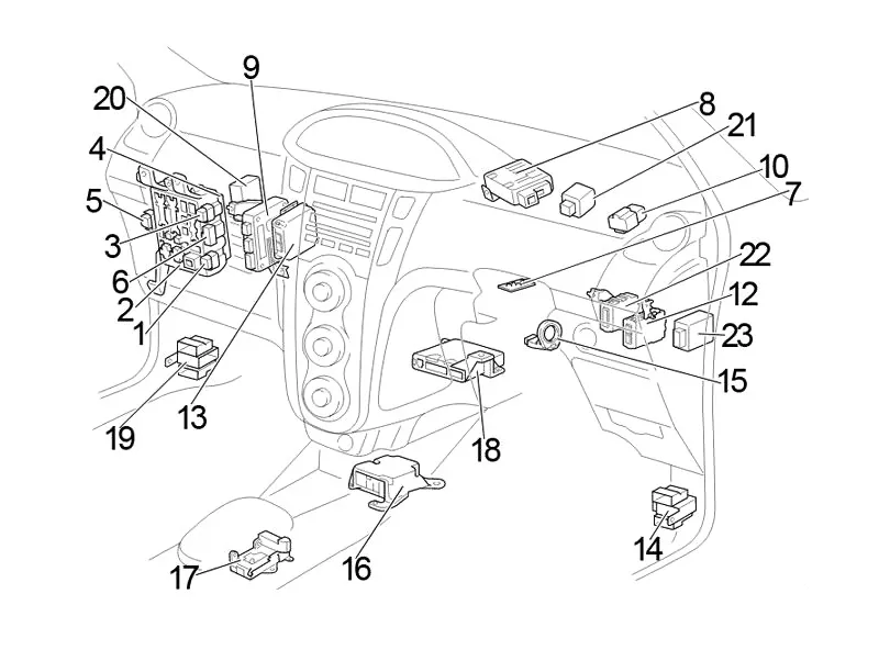
General layout of control units in the cabin
Left hand drive
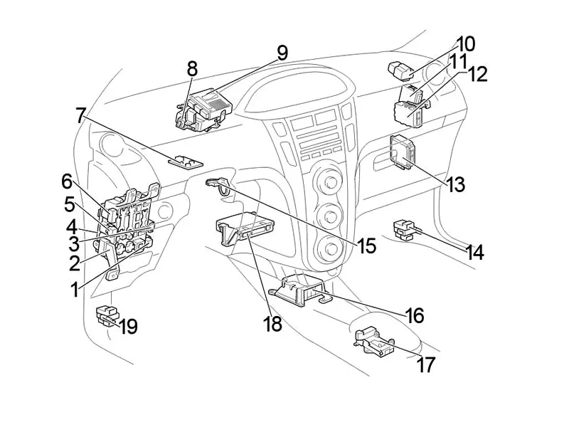
- Rear Fog Light Relay
- Fuse box
- Front Fog Light Relay
- Main Body ECU
- with entry and start system: auxiliary relay (ACC)
without entry and start system: auxiliary relay (ACC Cut) - Additional fuse box
- Steering lock ECU
- Power steering ECU
- ECU of multi-mode manual transmission
- Starter relay (ST CUT)
- LHD: Daytime Running Light Relay
- Power Management ECU
- Engine stop and start control unit
- Junction block
- Transponder key amplifier
- Airbag Sensor Assembly Center
- Gearshift Lock ECU
- Air conditioner booster
- Junction block
- RHD: Theft Warning System ECU
- RHD: Direction indicator
- RHD: Theft Warning Control Module (TMC, manufactured since August 2008)
- RHD: Dual Door Lock ECU
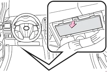
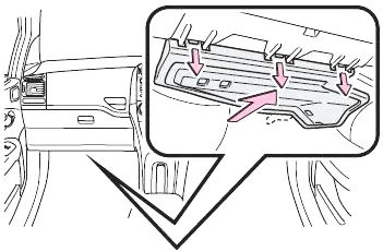
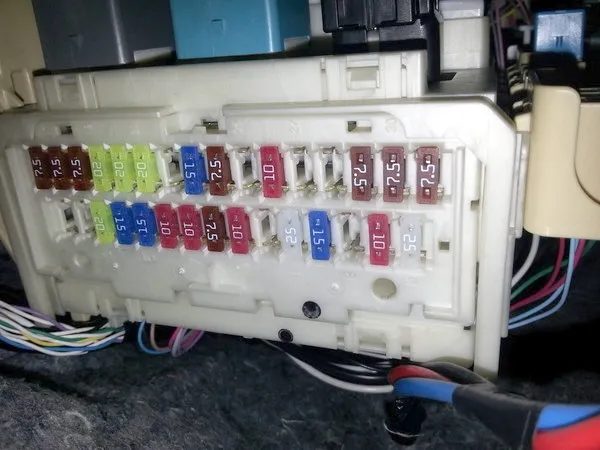
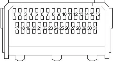
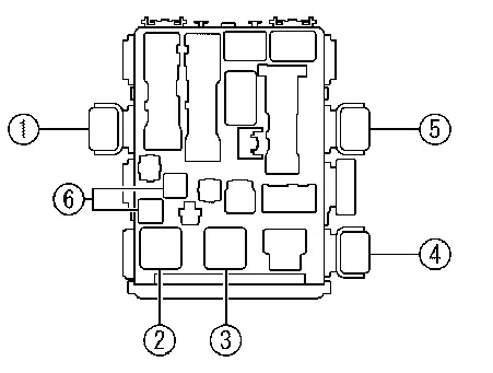
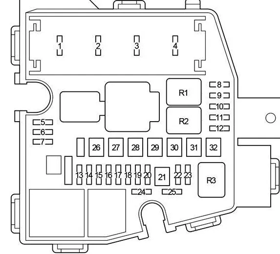
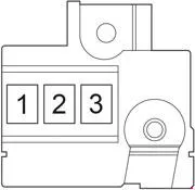
Fuse box
It is located under the instrument panel; to access it, you need to remove the protective cover.
Left hand drive
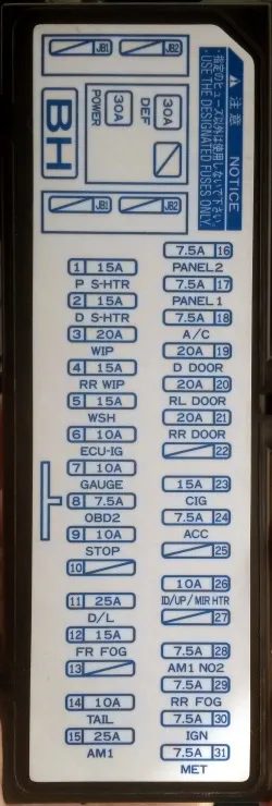
| 1 | 10A TAIL – Side marker lights, side marker lights, tail lights, number plate light, multiport fuel injection system/sequential multiport fuel injection system |
| 7.5A PANEL2 – Engine immobilizer system, entry and start system, front fog light, lighting, light reminder, multi-mode manual transmission, rear fog light, start, steering lock, tail light, wireless door lock control | |
| 2 | 7.5A PANEL1 – Lighting, instrument panel lighting control, meter and gauge |
| 3 | 7.5A A/C – Rear window defogger, air conditioning system |
| 4 | 20A D DOOR – Window lifter |
| 5 | 20A RL DOOR – Rear Passenger Electric Window (Left Side) |
| 6 | 20A RR DOOR – Rear Passenger Electric Window (Right Side) |
| 7 | – |
| 8 | 15A CIG – Cigarette Lighter, Socket |
| 9 | 7.5A ACC – Door lock system, outside rear view mirrors, audio system |
| 10 | – |
| 11 | 10A ID/UP /MIR HTR – Multiport fuel injection system / Sequential multiport fuel injection system / Heated mirrors |
| 12 | |
| 13 | |
| 14 | 7.5A RR FOG – Rear Fog Lights |
| 15 | 7.5A IGN – Multiport fuel injection system/sequential multiport fuel injection system, engine immobilizer system, SRS airbag system, front occupant classification system |
| 16 | 7.5A MET – Instruments and Sensors |
| 17 | 15A P S-HTR – Seat heating |
| 18 | 15A D S-HTR – Seat heating |
| 19 | 20/25A WIP – Windscreen Wiper |
| 20 | 15A RR WIP – Rear Windscreen Wiper |
| 21 | 15A WSH – Windshield Washer |
| 22 | 10A ECU-IG – Daytime running light system, anti-lock brake system, electric power steering system, electric windows, door lock system, anti-theft system, electric cooling fan |
| 23 | 10A GAUGE – Charging system, Direction indicators, Hazard warning lights, Lift lights, Instrument panel light control, Shift lock system, Rear window defogger, Air conditioning system, Automatic transmission system |
| 24 | 7.5A OBD2 – On-Board Diagnostics |
| 25 | 10A STOP – Brake lights, high-mounted brake light, multiport fuel injection system/sequential multiport fuel injection system, shift lock system, anti-lock brake system |
| 26 | – |
| 27 | 25A D/L – Door Lock System |
| 28 | 15A FR FOG – Front fog lights |
| 29 | – |
| 30 | 10A TAIL – Side marker lights, side marker lights, tail lights, number plate light, multiport fuel injection system/sequential multiport fuel injection system |
| 31 | 25A AM1 – Multi-port fuel injection system / sequential multi-port fuel injection system |
The cigarette lighter is controlled by fuse number 8 for 15A, marked on the cover as CIG.
Individual elements are attached to the top of the block.
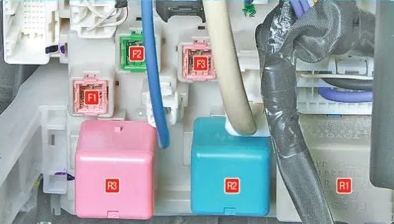
| F1 | 30A Body Equipment ECU Unit / Window Electrics |
| F2 | 30/40A Power supply for the turn signal relay/Rear window heating, fuse: “MIR HTR” |
| F3 | 30A Seat heating |
| R1 | Relay – turn signal interrupter |
| R2 | Heater relay |
| R3 | Relay “IG1” – ignition system |
Some relays can be mounted nearby:
- ACC relay
- Ignition system relay
- Heater relay
- Rear Fog Light Relay
- Front Fog Light Relay
- Fuses
Additional fuse box
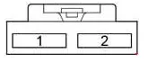
| 1 | 7.5A ACC2 – Shift Lock System |
| 7.5A AM2 NO.2 – Charging, Door Lock Control, Double Locking, Engine Management, Engine Immobilizer System, Entry & Start System, Ignition, Interior Light, Light Reminder, Electric Window, Seat Belt Warning, Start, Steering Lock, Wireless Door Lock Control | |
| 7.5A WIP-S – Charging System | |
| 2 | 7.5A ACC2 – Shift Lock System |
| 7.5A AM2 NO.2 – Charging, Door Lock Control, Double Locking, Engine Management, Engine Immobilizer System, Entry & Start System, Ignition, Interior Light, Light Reminder, Electric Window, Seat Belt Warning, Start, Steering Lock, Wireless Door Lock Control | |
| 7.5A WIP-S – Charging System |
Additional elements
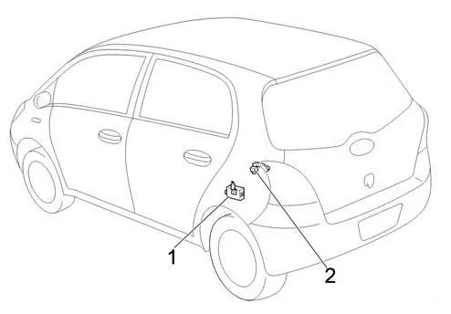
- Door control receiver
- Brake light relay
Blocks under the hood
Location
General layout of electrical control units under the hood
Left hand drive
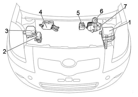
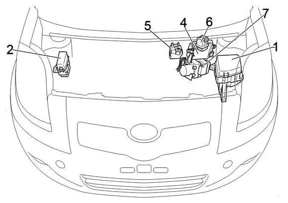
- Fuse and relay box
- without daytime running lights: relay box
- with daytime running lights: relay block no. 2
- Engine ECU
- Fuse block
- Glow Plug Relay
- Anti-skid control unit with drive
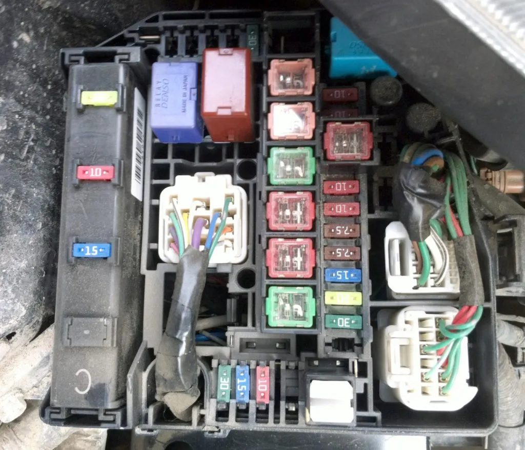
Fuse and relay box
Located on the left side of the engine compartment.
Photo – example
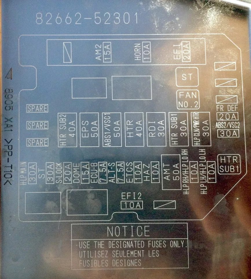
| 1 | – |
| 2 | 15A AM2 – Starting system, multipoint fuel injection system / sequential multipoint fuel injection system |
| 3 | 20A EFI – Multiport Fuel Injection System / Sequential Multiport Fuel Injection System |
| 10A HORN – 1NZ-FE, 2NZ-FE, 2SZ-FE, 2ZR-FE, 1KR-FE: Horn | |
| 30A ECD – 1ND-TV: Multiport fuel injection system / sequential multiport fuel injection system | |
| 4 | 10A HORN – 1KR-FE, 1ND-TV: Horn |
| 20A EFI – 1NZ-FE, 2NZ-FE, 2SZ-FE, 2ZR-FE, 1KR-FE: Multi-port fuel injection system / Sequential multi-port fuel injection system | |
| 30A ECD – Diesel: Multi-port fuel injection system / Sequential multi-port fuel injection system (TMMF, production from November 2008) | |
| 5 | Spare fuse |
| 6 | Spare fuse |
| 7 | Spare fuse |
| 8 | |
| 9 | |
| 10 | |
| 11 | 20A FR DEF – Front glass heating |
| 12 | 30A ABS2/VSC2 – Anti-lock braking system, vehicle stability control system |
| 13 | 30A H-LP MAIN – with DRL: “H – LP LH / H – LP LO LH”, “H – LP LH / H – LP LO LH”, “H – LP HI LH”, “H – LP HI RH” |
| 14 | 30A ST – Starting System |
| 15 | 20A S-LOCK – Steering Lock System |
| 16 | 15A DOME – Interior Lighting, Personal Lighting, Anti-Theft System, Audio System, Wireless Remote Control System |
| 17 | 7.5A ECU-B – Engine immobilizer system, daytime running light system, front occupant classification system, power windows, door lock system, theft deterrent system, counter and sensor |
| 18 | 7.5A ALT-S – Charging System |
| 19 | 10A ETCS – Multiport fuel injection system / sequential multiport fuel injection system, electronic throttle control system |
| 20 | 10A HAZ – Direction indicators, emergency flashers |
| 21 | 50A AMT – Multi-mode Manual Transmission |
| 40A BBC – Stop and Start System | |
| 22 | 10A H-LP RH – Right Headlight |
| 23 | 10A H-LP LH – Left Headlight |
| 24 | 10A EFI2 – Gasoline: Multiport fuel injection system / Sequential multiport fuel injection system |
| 10A ECD2 – Diesel: Multi-port fuel injection system / Sequential multi-port fuel injection system | |
| 25 | 7.5A ECD3 – Diesel: Multi-port fuel injection system / Sequential multi-port fuel injection system |
| 26 | 40A HTR SUB2 – 435W Type: PTC Heater |
| 50A HTR SUB1 – 600W Type: PTC Heater | |
| 27 | 50A EPS – Electric Power Steering |
| 28 | 50A ABS1/VSC1 – Anti-lock braking system, vehicle stability control system |
| 29 | 40A HTR – Air Conditioning System |
| 30 | 30A RDI – Electric Cooling Fan |
| 31 | 30A HTR SUB1 – 435W Type: PTC Heater |
| 30A HTR SUB2 – 600W Type: PTC Heater | |
| 32 | 30A H-LP CLN //PWR HTR – Electric Heater, Headlight Washer |
| 30A HTR SUB3 – 600W Type: PTC Heater | |
| Relay | |
| R1 | Starter (ST) – Starter |
| R2 | Electric cooling fan (FAN NO.2) – Cooling fan |
| R3 | PTC heater (HTR SUB1) – Heater |
Relay block
Scheme
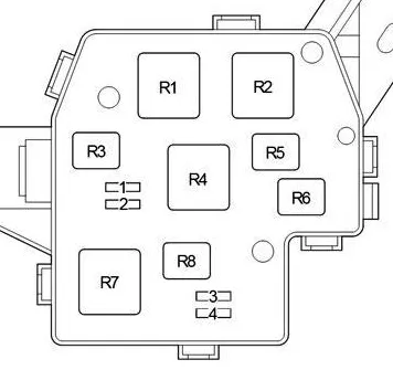
| 1 | – |
| 2 | – |
| 3 | 10A H-LP HI RH – Front Right Headlight |
| 4 | 10A H-LP HI LH – Front Left Headlight |
| Relay | |
| R1 | Dimmer (DIM) |
| R2 | Vehicle Stability Control / Anti-lock Braking System / Multi-Mode Manual Transmission (VSC1 / ABS1 / AMT) |
| R3 | – |
| R4 | Headlight (H-LP) |
| R5 | PTC heater (HTR SUB3) |
| R6 | PTC heater (HTR SUB2) |
| R7 | PTC heater (HTR SUB1) |
| R8 | Vehicle Stability Control/Anti-lock Braking System (VSC2/ABS2) |
Additional relay block
Option 1
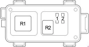
- R1 Vehicle Stability Control (VSC1)
- R2 Vehicle Stability Control (FR DEF / VSC2)
Option 2
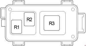
- Heater R1 PTC (HTR SUB3)
- Heater R2 PTC (HTR SUB2)
- R3 Headlight / Multi-mode Manual Transmission / PTC Heater (H-LP / AMT / HTR SUB1)
Power fuse box
It is located on the positive terminal of the battery.
- 80A GLOW DC/DC – Diesel: Multi-port fuel injection system / Sequential multi-port fuel injection system
- 60/80A MAIN – Fuses “EFI”, “HORN”, “AM2”, “ALT-S”, “DOME”, “ST”, “ECU-B”, “ETCS”, “HAZ”, “H-LP LH/H-LP LO LH”, “H-LP RH/H-LP LO RH”, “AMT”
- 120A ALT – Charging System, Fuses HTR SUB2″, “EPS”, “ABS1/VSC1”, “HTR”, “ABS2/VSC2”, “HTR SUB1”, “RDI”, “DEF”, “FR FOG”, “OBD2”, “D/L”, “POWER”, “RR DOOR”, “RL DOOR”, “STOP” and “AM1” fuses