Chevrolet Orlando is a family seven-seater compact van. It was produced by GM Korea for the international market. The model debuted in 2009 at the Paris Motor Show, although the original idea of this car – a 7-seater concept car based on the Cruze sedan – was presented to the public even earlier, in 2008. In this material, we will analyze in detail the fuse diagrams of the first generation Chevrolet Orlando (body J309 ) of 2009, 2010, 2011, 2012, 2013, 2014, 2015 release.

Here you will find the locations and photos of the mounting blocks. We will separately note the fuses responsible for the cigarette lighter and fuel pump.
All electrical equipment
General layout of electrical equipment.
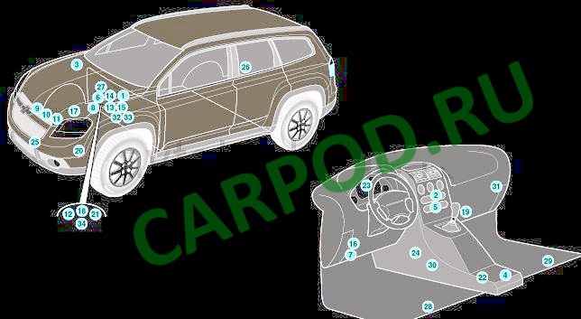
| No. | Component |
| 1 | Electronic ABS control module |
| 2 | Electronic air conditioning control module |
| 3 | Anti-theft system control unit – in the center console |
| 4 | Anti-theft alarm sound signal |
| 5 | Audio system |
| 6 | AKB |
| 7 | Diagnostic connector |
| 8 | Electronic Engine Control Module (ECM) |
| 9 | Fog Light Relay (Connected to Engine Compartment Fuse/Relay Box 1) |
| 10 | Fuse/Relay Box, Underhood 1 |
| 11 | Fuse/Relay Box, Underhood 2 |
| 12 | Fuse/Relay Box, Underhood 3 |
| 13 | Fuse/Relay Box, Underhood 4-Diesel |
| 14 | Fuse/Relay Box, Instrument Panel |
| 15 | Glow Plug Control Module |
| 16 | High beam headlight relay (connected to engine compartment fuse/relay box 1) |
| 17 | Heater Blower Motor Resistor – Near the blower motor |
| 18 | Sound signal – behind the left wheel arch lining |
| 19 | Horn relay (connected to engine compartment fuse/relay box 1) |
| 20 | Electronic immobilizer control unit – under the center console |
| 21 | Instrument cluster control module |
| 22 | Multifunctional control unit – functions: Central locking, exterior lighting, interior lighting, seat belt monitoring system |
| 23 | Ambient air temperature sensor |
| 24 | Parking system control module – in the right part of the luggage compartment |
| 25 | Power Steering Control Module |
| 26 | Driver Seat Heating Control Module – Under Driver Seat |
| 27 | Passenger Seat Heating Control Module – Under Passenger Seat |
| 28 | SRS Electronic Control Module |
| 29 | Phone control module |
| 30 | Electronic transmission control unit (TCM) – on the transmission |
| 31 | Vehicle speed sensor – on transmission |
| 32 | Windshield Washer Pump Relay (Connected to Engine Compartment Fuse/Relay Box 1) |
In the salon
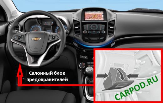
It is located behind the glove compartment on the driver’s side. To access it, you need to: Open the glove compartment. Squeeze it from the sides. Then lift it up so that it detaches and take it out.
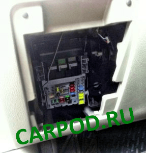
Example of access.
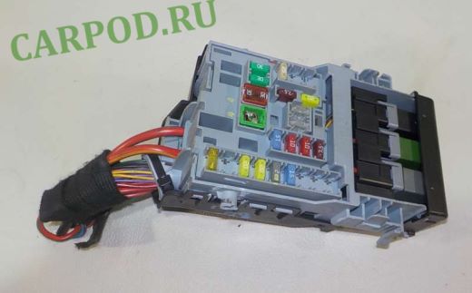
General view of the block.
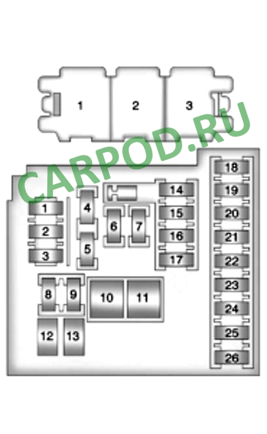
| No. | Description | Current, A |
| 1 | No | — |
| 2 | No | — |
| 3 | Body controller | 25 |
| 4 | Radio | 20 |
| 5 | Parking Assist Control Module, Sounder, Steering Column Shift Paddle – Center Console, Display | 7.5 |
| 6 | Orlando Front Cigarette Lighter | 20 |
| 7 | Power socket | 20 |
| 8 | Body controller | 30 |
| 9 | 30 | |
| 10 | 30 | |
| 11 | Door control module, Electric fan | 40 |
| 12 | No | — |
| 13 | Seat Heating Control System Module | 25 |
| 14 | Diagnostic connector, oil supply nipple | 7.5 |
| 15 | Airbag diagnostic and control module | 10 |
| 16 | Rear Compartment Door Release Relay | 10 |
| 17 | HVAC Control Unit / HVAC Control Panel Assembly | 15 |
| 18 | Not used | — |
| 19 | — | |
| 20 | — | |
| 21 | Instrument cluster | 15 |
| 22 | Ignition switch | 2 |
| 23 | Body controller | 20 |
| 24 | 20 | |
| 25 | No | — |
| 26 | Auxiliary power outlet (cigarette lighter at rear) | 20 |
| R1 | Trunk/Tailgate Opening Relay | |
| R2 | Battery current monitoring relay | |
| R3 | Relay for additional equipment circuits (cigarette lighter, sockets) |
In the engine compartment
Main block
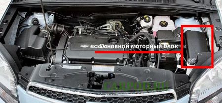
It is located on the left side of the engine compartment, next to the battery. To access it, you need to move 3 latches from the cover and remove it.
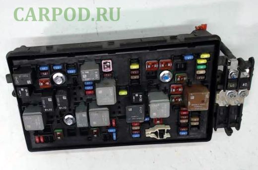
General view of the main block.
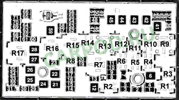
| No. | Purpose of the relay | |
| R1 | Air Conditioning Compressor Clutch | |
| R2 | Starter | |
| R3 | Cooling fan | |
| R4 | Windshield wiper speed control | |
| R5 | Windscreen wiper | |
| R6 | No | |
| R7 | Transmission | |
| R8 | Fuel module (fuel pump) | |
| R9 | Average speed of 1 cooling fan | |
| R10 | Medium speed 2 cooling fan | |
| R11 | No | |
| R12 | Cooling fan speed control (or in the relay block – under the hood) | |
| R13 | Cooling Fan High Speed Relay | |
| R14 | No | |
| R15 | Main Ignition Relay | |
| R16 | Fuel heater relay | |
| R17 | Rear window anti-fog | |
| Maintenance-free printed circuit board (PCB) relays inside the unit. | ||
| — | Horn relay | |
| — | Windshield Washer Pump Relay | |
| — | Front Fog Light Relay | |
| — | Headlight high beam relay | |
| No. | Decoding fuses | Current, A |
| 1 | Gearbox control unit | 15 |
| 2 | Engine control unit | 15 |
| 3 | No | — |
| 5 | Transmission control module, engine control module, mass air flow and intake air temperature sensor, transmission secondary shaft speed sensor | 15 |
| 6 | Windscreen Wiper Relay | 30 |
| 7 | No | — |
| 8 | Fuel injectors | 15 |
| 9 | Ignition coil, fuel injectors | 15 |
| 10 | Engine Control Module, Gearbox Secondary Shaft Speed Sensor | 15 |
| 11 | Heated lambda sensors | 10 |
| 12 | Starter motor | 30 |
| 13 | EVAP Canister Bleed Solenoid Valve | 7.5 |
| 14 | No | — |
| 15 | No | — |
| 16 | Air quality sensor | 7.5 |
| 17 | Airbag diagnostic and control module | 5 |
| 18 | Fuel Pump Control Module | 10 |
| 19 | No | — |
| 20 | Fuel pump relay | 20 |
| 21 | Window drive motors, front door | 30 |
| 22 | No | — |
| 23 | No | — |
| 24 | Window drive motors, front door | 30 |
| 25 | No | — |
| 26 | Electronic Brake Control Unit (EBCM) | 40 |
| 27 | Door Lock Remote Control Receiver | 30 |
| 28 | Rear anti-fog mesh | 40 |
| 29 | No | — |
| 30 | Electronic Brake Control Unit (EBCM) | 15 |
| 31 | Body controller | 20 |
| 32 | 20 | |
| 33 | Seat Heating Control System Module | 30 |
| 34 | Sunroof Control Module | 25 |
| 35 | Audio amplifier | 30 |
| 36 | No | — |
| 37 | Headlight – right high beam | 10 |
| 38 | Headlight – left high beam | 10 |
| 39 | No | — |
| 40 | No | — |
| 41 | No | — |
| 42 | Radiator Fan Relay, Radiator Fan Motor | 20/30 |
| 43 | No | — |
| 44 | No | — |
| 45 | Radiator Fan High Speed Relay, Radiator Fan Motor | 30/40 |
| 46 | Cooling Fan Relay | 10 |
| 47 | Heated Oxygen Sensors, Throttle Body | 10 |
| 48 | Fog lights, front | 15 |
| 49 | No | — |
| 50 | No | — |
| 51 | Beep | 15 |
| 52 | Instrument cluster | 5 |
| 53 | Interior rear view mirror | 10 |
| 54 | Headlight switch, auxiliary electric heater, HVAC control module | 5 |
| 55 | Window switches, front, mirror switch | 7.5 |
| 56 | Windshield washer pump | 15 |
| 57 | Steering Column Lock Control Module | 15 |
| 58 | No | — |
| 59 | Fuel heater | 30 |
| 60 | Exterior rear view mirrors | 7.5 |
| 61 | No | — |
| 62 | A/C Compressor Clutch Relay, A/C Compressor Clutch | 10 |
| 63 | No | — |
| 64 | Airbag diagnostic and control module | 5 |
| 65 | No | — |
| 66 | No | — |
| 67 | Fuel Pump Control Module | 20 |
| 68 | No | — |
| 69 | Body controller | 5 |
| 70 | Rain sensor | 5 |
| 71 | No | — |
Additional blocks
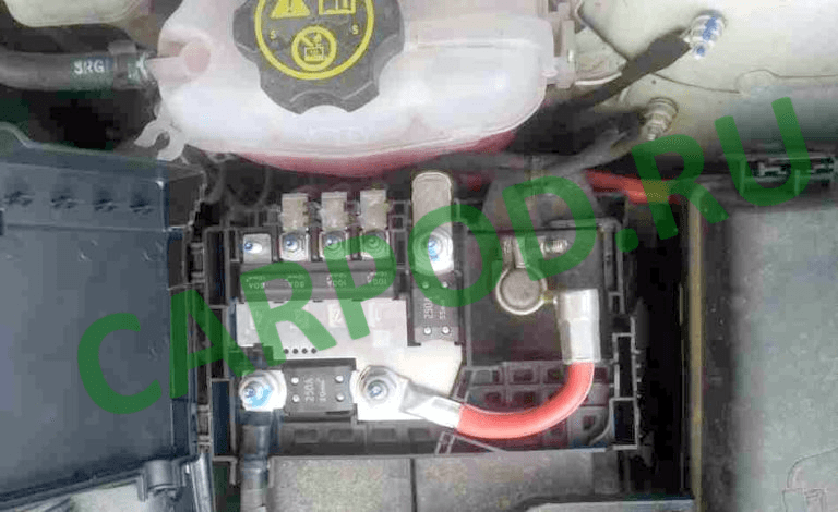
On the battery cover there is a block with high-power fuse links.
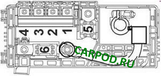
| No. | Description | Current, A |
| 1 | Mounting block in the cabin | 100 |
| 2 | 100 | |
| 3 | Electric Power Steering (EPS) (NJ1) | 80 |
| 4 | No | — |
| 5 | Fuse Block – Auxiliary Battery | 250 |
| 6 | Starter motor | 250/500 |
| Additional block on the battery (diesel only) | ||
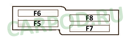
| F5 | Glow plugs | 80 |
| F6 | Additional heater | 100 |
| F7 | – | – |
| F8 | – | – |
Depending on the vehicle configuration, there may be a separate engine block with relay modules.
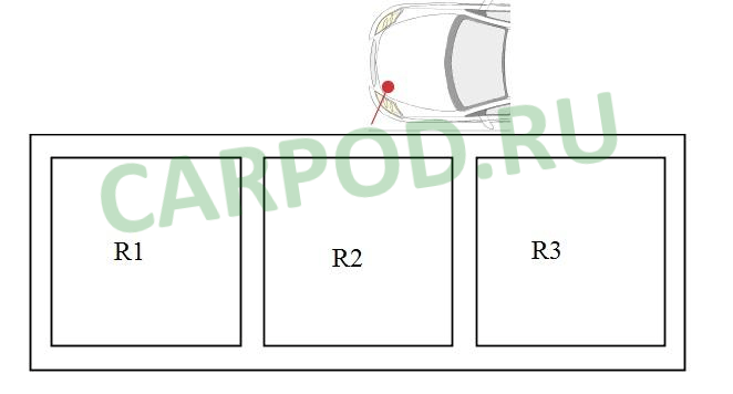
| No. | Purpose of the relay |
| R1 | low cooling fan speed. |
| R2 | |
| R3 | Cooling Fan Speed Control |