Renault Koleos 2nd generation was produced in 2016, 2017, 2018, 2019, 2020, 2021, 2022, 2023, 2024. During this time, the model was updated. In our material you will find a description of the fuses and relays of Renault Koleos 2 with block diagrams, their locations and photo examples of execution. Note the fuse responsible for the cigarette lighter.

The location of the blocks, as well as their purpose, may differ from that shown and depends on the year of manufacture, the level of electrical equipment and the region of delivery of your car.
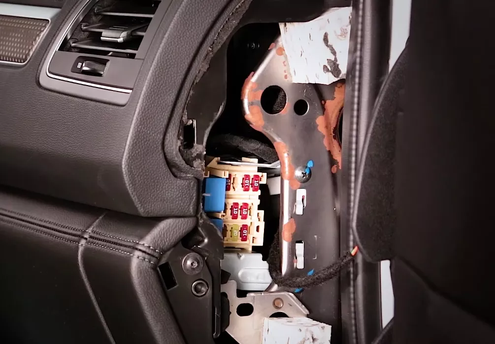
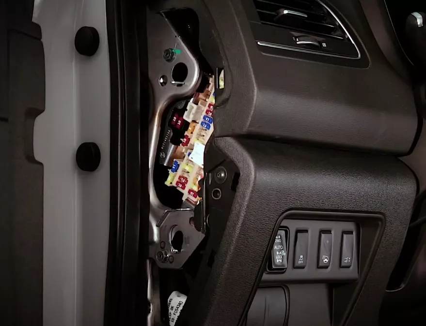
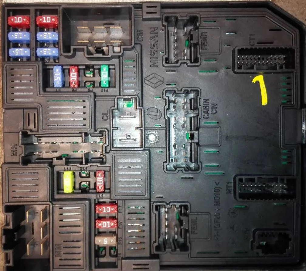
Blocks in the cabin
There can be 2 main fuse boxes installed in the passenger compartment: on the left and right sides of the instrument panel (at the end, behind the protective cover.)
Right block
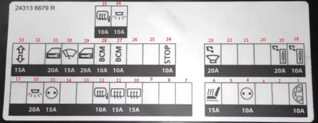
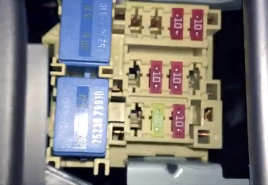
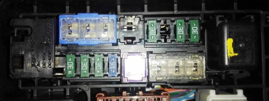
Main block
| No. | A | Description |
|---|---|---|
| 1 | 10A | Double-acting windshield and rear window washer pump (677) via steering column switch unit (1519), Instrument panel |
| 2 | 10A | Fuse in the modification with heated steering wheel: power supply circuits of fuse f3 on the board |
| 3 | ||
| 4 | 10A | Additional equipment socket |
| 5 | ||
| 6 | 15A | Heated seats |
| 7 | 20A | Heater, A/C Booster, Engine Restart Baypass Control |
| 8 | ||
| 9 | ||
| 10 | 15A | Rear window heating |
| 11 | 15A | Rear window heating |
| 12 | 10A | Heated mirrors |
| 13 | 10A | ABS or brake lights |
| 14 | 20A | |
| 15 | 15A | Cigarette lighter |
| 16 | 20A | Interior lighting |
| 17 | 20A | Heater motor, resistor, air conditioner amplifier |
| 18 | 10A | Audio system |
| 19 | 20A | Audio system, navigation control unit, all-round camera |
| 20 | 5A | Body Control Module (BCM), Siren, Multi-Function Switch |
| 21 | ||
| 22 | ||
| 23 | 20A | Audio |
| 24 | 10A | Brake Light Switch, Body Control Module (BCM) |
| 25 | 5A | All-wheel drive, anti-theft system antenna amplifier |
| 26 | ||
| 27 | 10A | Body Control Module (BCM), Multi-Function Switch |
| 28 | 10A | Body Control Module (BCM), Electric Parking Brake, Diagnostic Port, All Wheel Drive, Instrument Panel/Switch Lights, Power Window Relay, Mirror Folding Relay, Mirror Opening Relay |
| 29 | 20A | Central locking, body control module (BCM) |
| 30 | 15A | Glass washer |
| 31 | 20A | Central locking, body control module (BCM) |
| 32 | ||
| 33 | 15A | Hazard warning lights and direction indicators |
| 34 | 10A | Interior lighting |
| 35 | 10A | Heating |
Fuse number 15 is responsible for the cigarette lighter.
The individual relay elements are located on the back side of the unit.
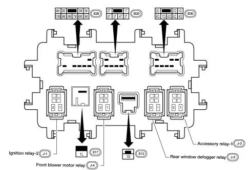
- Ignition system relay
- Front Engine Fan Relay
- Rear window heating relay
- Auxiliary relay after ignition switch
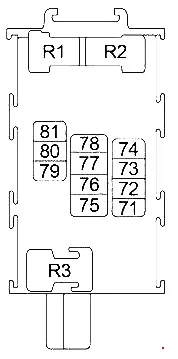
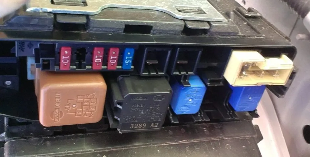
Additional block
| No. | A | Purpose |
|---|---|---|
| 71 | 10A | Steering wheel angle sensor |
| 72 | 10A | Instrument cluster |
| 73 | 10A | Audio system, navigation control unit, all-round camera |
| 74 | 10A | Transmission Control Module (TCM) |
| 75 | – | |
| 76 | 10A | Air conditioner control unit, air conditioner amplifier |
| 77 | 10A | ABS |
| 78 | – | |
| 79 | 10A | Oil pump relay |
| 80 | 20A | Audio system, navigation control unit, all-round camera |
| 81 | 10A | Transmission Control Module (TCM) |
| Relay | ||
| R1 | Auxiliary relay | |
| R2 | Ignition | |
Some additional elements may be installed separately, under the panel. For example, fuses: Oil pump relay and Transmission Control Module (TCM).
Blocks under the hood
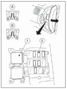
Mounting blocks
They are located under the hood in the engine compartment on the left side, under the air intake pipe.
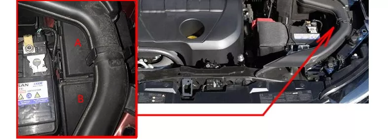
To access the blocks, you need to remove the air intake pipe.
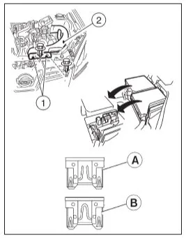
- A – requires replacement
- B – whole fuse
Block A
Check the designation against your diagrams on the block cover.
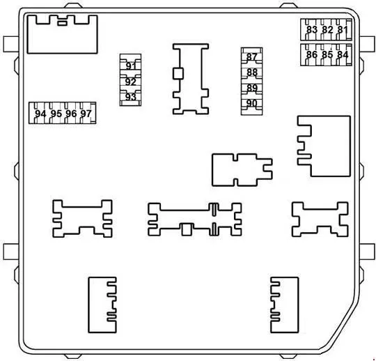
| No. | A | Designation |
|---|---|---|
| 81 | 10A | Engine control unit (injection ECU) |
| 82 | 15A | Engine Control Unit (Injectors) |
| 83 | 15A | Throttle body, engine control module, EVAP canister valve, mass air flow sensor, ignition coils, main relay, exhaust valve, intake valve, high pressure fuel pump, injectors, fuse box in the engine compartment, air-fuel ratio sensor, fuel heater, water in fuel sensor, coolant bypass valve |
| 84 | 10A | Engine control unit, intake manifold valve, exhaust timing valve, intake timing valve, intermediate timing valve |
| 85 | 15A | Air fuel ratio sensor, heated oxygen sensor, turbo boost valve, engine control unit, glow plug control unit |
| 86 | 15A | Injectors, ignition coils, fuse box |
| 87 | 15A | Air Conditioning Compressor Relay |
| 88 | 10A | ABS |
| 89 | 15A | Coolant pump |
| 90 | 30A | Front Wiper Relay, Front Wiper Motor |
| 91 | 20A | Fuel pump relay |
| 92 | 30A | Starter |
| 93 | 10A | Engine Control Module, Transmission Control Module, Transmission Range Sensor, Engine Compartment Fuse Box, Neutral Position Sensor, Primary Speed Sensor, Secondary Speed Sensor, RPM Sensor, Reverse/Neutral Sensor |
| 94 | 5A | EPS |
| 95 | 5A | Steering wheel lock unit |
| 96 | 10A | Restart Relay (Start-Stop) / ABS |
| 97 | 10A | Front right combination light, front left combination light, compressor, transmission range sensor, engine compartment fuse box, neutral position switch, reverse speed switch, reverse/neutral switch |
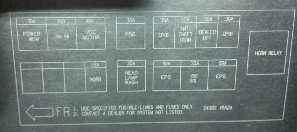
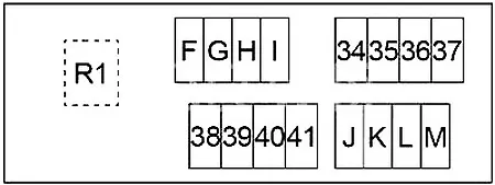
Block B
| No. | A | Designation |
|---|---|---|
| 34 | 15A | Horn relay |
| 35 | 30A | Diesel: PTC Relay 2 |
| 36 | 30A | Diesel: PTC 3 Relay |
| 37 | 30A | Diesel: PTC Relay 1 |
| 38 | 30A | Electric parking brake |
| 39 | 30A | Optional connector |
| 40 | – | |
| 41 | 30A | Electric parking brake |
| F | 50A | ESP |
| G | 30A | ABS |
| H | 50A | ESP |
| I | 30A | Headlight Washer Relay |
| J | – | |
| K | 40A | ABS |
| L | 30A | Starter relay, ignition relay (fuses: “1”, “2”, “3”, “4”, “10”, “11”, “12”) |
| M | 50A | Window lifter relay, window lifters, curtain, electric seats |
| R1 | Horn relay |
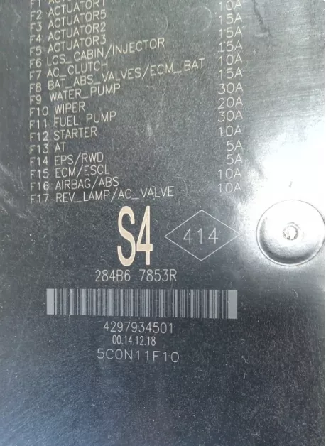
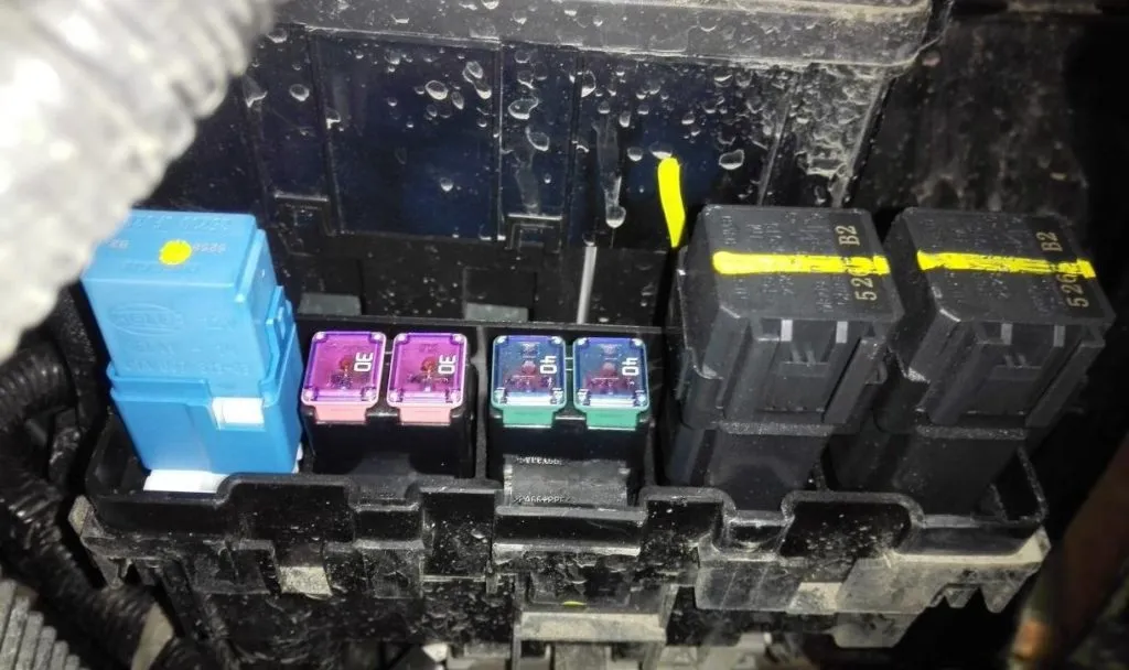
Additional blocks
Additional blocks with fuses and relays can be installed separately under the hood.
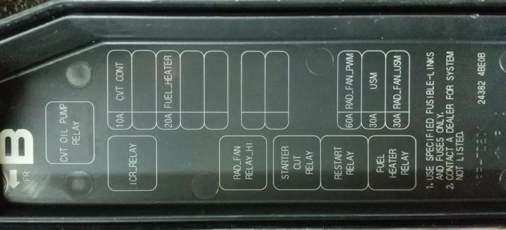
| No. | Purpose |
|---|---|
| CVT OIL PUMP RELAY | transmission oil pump relay |
| CVT CONT | Automatic transmission ECU |
| FUEL HEATER | fuel heating |
| RAD FAN | radiator fan |
| STARTER RELAY | starter relay |
| USM | fuse box and relay under the hood |
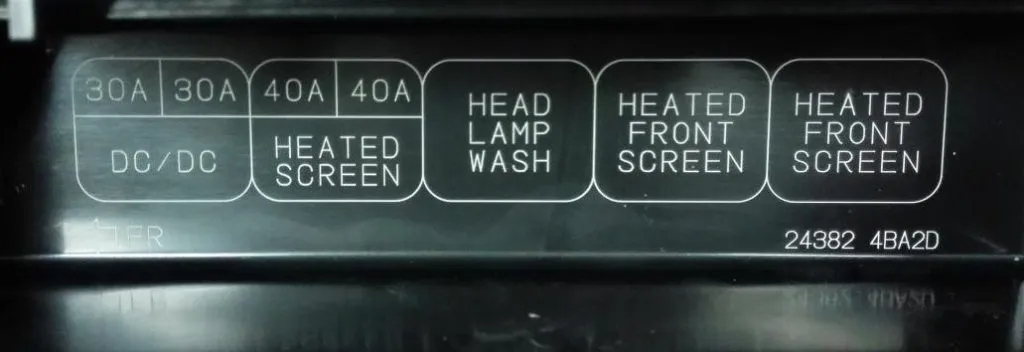
| No. | Designation |
|---|---|
| HEATED SCREEN | Glass heating |
| H/LAMP WASHER RELAY | Headlight Washer Relay |
| ANTI-THEFT HORN RELAY | Anti-theft alarm horn relay |
| HEATED FRONT SCREEN RELAY | Windshield heating relay |
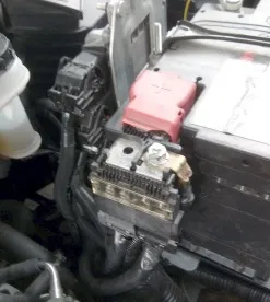
Power fuse box
It is located on the positive terminal of the battery and consists of high-power fuse links.
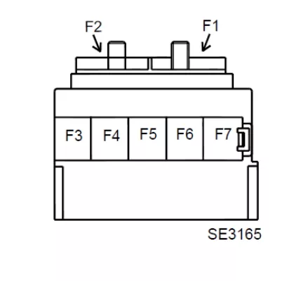
| No. | A | Purpose |
|---|---|---|
| F1 | 450A | Starter |
| F2 | 450A | Generator |
| F3 | 100A | Fuse for power supply circuits of fuses F1, F2, F3, F4, F5, F6, F7, F8, F9, F10, F11, F12, F13, F14, F15 and F16 on the board (777) – power supply circuits of fuses F1 and F2 on the board (1793) in the “MICROHYBRID” modification |
| F4 | 100A | Protection and Communication Block (1337) – Power Circuits for Fuse F4 on the Board (1792) |
| F5 | 50A | Additional interior heater |
| F6 | 100A | Relay after ignition switch, Glass heating, Power supply circuits of fuses F1, F2, F3, F4, F5, F6, F7, F8, F9, F10, F11, F12, F13, F14, F15, F16 and F22 on the board (260) |
| F7 | 100A | Protection and communication unit (1337) |