Volkswagen Beetle A5 is also known as the Beetle. Another car has the same nickname – Volkswagen New Beetle . However, these are different models. In our material you can find a description of fuses and relays Volkswagen Beetle (Beetle) with photos and block diagrams for cars manufactured in 2011, 2012, 2013, 2014, 2015, 2016, 2017, 2018, 2019, 2020, 2021, 2022, 2023, 2024, 2025, 2026, 2027, 2028, 2021, 2022, 2023, 2022, 2023, 2024, 2025, 2026, 2027, 2028, 2029, 2020, 2021, 2022, 2021, 2022, 2022, 2023, 2022, 2023, 2024, 2025.
The number of fuses in the blocks and their purpose may vary and depend on the year of manufacture and configuration of the Volkswagen Beetle.
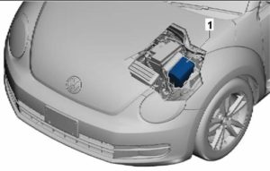
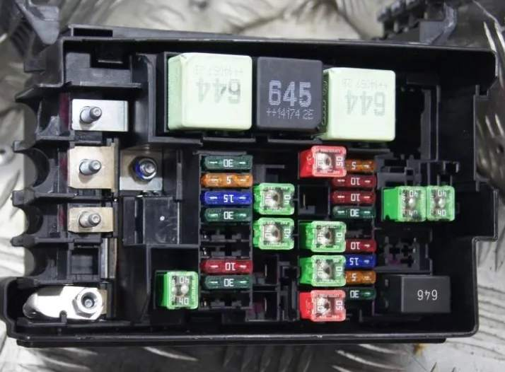
Block under the hood
It is located next to the battery, under a protective cover.
Description
High power fuse links
- 200A – Generator
- Reserve
- 80A – Power steering control unit
- 80A – Fuses
Fuses
- Reserve
- 20/30A – Engine control unit
- 5A – Radiator fan control unit
- 15A – Lambda probe
- 10A – Lambda probe, Electric fuel pump relay, Heating resistor relay, Boost pressure limit solenoid valve, Crankcase ventilation system heating resistor, Valve 1 of the gas distribution phase regulator, Turbocharger bypass valve, Intake manifold flap valve, Fuel system pump switch
- 10A – Fuel pump relay, Secondary air pump relay,
Engine electronic components power supply relay, Boost pressure limit solenoid valve, Adsorber solenoid valve, Intake manifold control valve, Oil pressure control valve - 20/30A – Throttle body, Ignition coil 1 with output stage, Ignition coil 2 with output stage, Ignition coil, Fuel pressure regulator, Fuel metering valve.
- 10A – Air flow meter, Fuel pump relay, Boost pressure limit solenoid valve, Adsorber solenoid valve 1, Valve 1 of the gas distribution phase regulator, Valve 2 of the exhaust gas recirculation system, Turbocharger bypass valve, Supercharger drive solenoid clutch, Pressure control valve Coolant circulation pump 2
- 10A – Coolant pump relay after engine shutdown, Glow plug control unit, Low heating power relay, High heating power relay, Additional cooling system pump relay, Engine electronic components power supply relay, Fuel pressure regulator, Coolant circulation pump 2
- 5A – Clutch pedal position sensor, Brake light switch
- Reserve
- Reserve
- 30A – Voltage stabilizer, Radio navigation system display control unit, Navigation system control unit,
Head unit - 10A – Motronic power supply relay, Terminal 30 power supply relay, Engine control unit
- 10A – Alarm siren relay
- 40A – Amplifier
- 15/30A – Mechatronic unit DSG gearbox
- 15A – Mechatronic unit DSG gearbox
- 5A – On-board network control unit (battery)
- 30A – On-board network control unit
- 40/50A – Heating element of the additional air heater, Electric motor of the secondary air pump
- 40A – Heating element of the additional air heater
- Reserve
- 40/50A – Relay 1 power supply terminal 75
- 40A – Power supply relay terminal 15
- 50A – Glow plug control unit
- 50A – Radiator fan control unit
- 20/30A – Fuel pump relay, Engine electronic components power supply relay
- Reserve
- 40A – ABS control unit
- 40A – ABS control unit
- 40A – Heating element of the additional air heater, Electric motor of the secondary air pump
Also here are individual relay elements: glow plugs, cooling fan, etc.
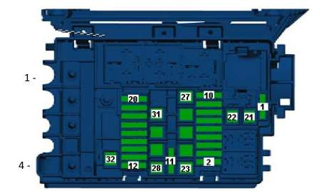
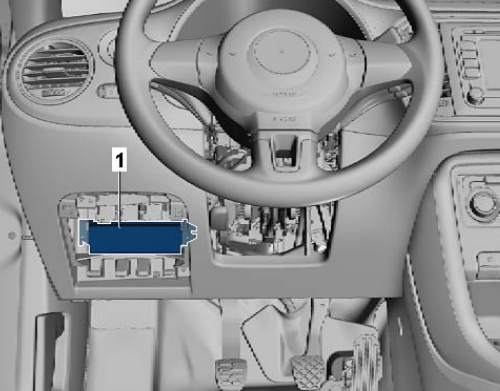
Cabin block
It is located under the dashboard on the driver’s side behind a protective cover.
Block layout diagram
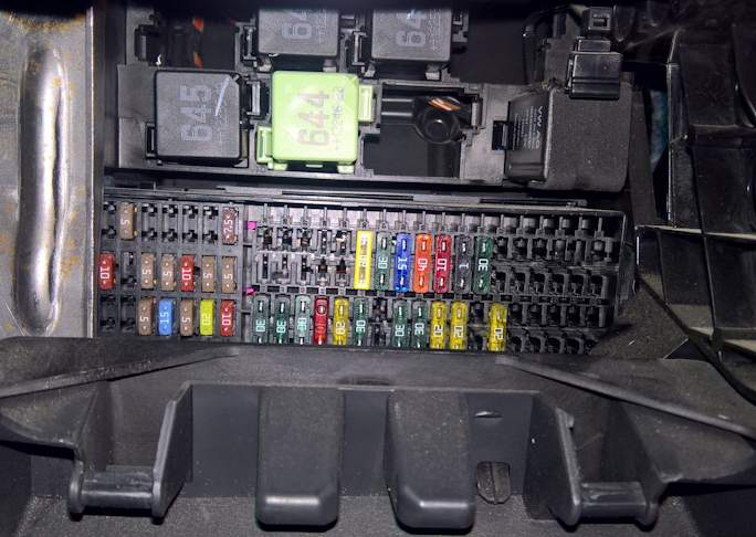
Please note that other relays are located here.
Fuse block diagram
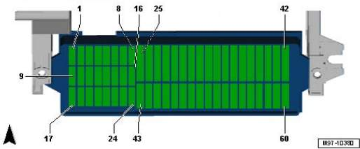
Appointment
- 5A – BO 2 blind spot control
- 10A – Emergency call module control unit and communication unit
- 5A – instrument cluster control unit
- 5A – Receiving – transmitting phone
- 10A – Instrument cluster control unit, On-board network control unit, Left fog lamp bulb
- 10A – Unlock button in the tailgate handle, Rear view camera
- 5A – Switch and instrument cluster backlight brightness control, License plate light
- 10A- Windshield washer pump
- 5A – Airbag control unit, Front passenger airbag off indicator lamp, Seat occupancy detection system control unit
- 15A – Intermittent wiper switch
- 5A – Light switch
- Reserve
- 5A – Start-stop mode button, Mirror folding switch, Tire pressure indicator button, Reverse light switch, High pressure sensor, Air pollution sensor, Heater control unit, Parking assistant control unit, Vehicle location tracking system control unit, Electric control, Washer nozzle heating resistor
- 10A – Cruise control switch, Tiptronic switch, Oil level and temperature sensor, Additional instruments, ABS control unit, Instrument cluster control unit, Power steering control unit, Steering column control unit, Voltage stabilizer, Data bus diagnostic interface, Fuel pump control unit, Selector sensor control unit, Engine control unit, Crankcase ventilation system heater resistor
- 5A – Switch and instrument cluster backlight brightness control, Air flow meter, Vibration suppression system control unit, Headlight range adjuster actuator motor, Connector, 16-pin, diagnostic connector.
- 5A – Engine control unit
- 10A – Interior security system sensor, Vehicle tilt sensor, Alarm siren
- 15A – Left dipped beam headlight bulb
- 15A – Right dipped beam headlight bulb
- 10A – Tiptronic switch, Heater control unit, Automatic transmission control unit
, Climatronic control unit, Air conditioning control unit, Selector sensor control unit, Ignition key removal lock solenoid - 15A – On-board network control unit
- 5A – Ignition and starter switch, Vehicle location tracking system control unit
- 10A – Rain and light sensor, On-board network control unit, Telephone transceiver, Emergency call module and communication unit control unit, Connector, 16-pin -T16- , diagnostic connector, Additional devices
- 10A – On-board network control unit, Engine access and start authorization system control unit, Steering column electric lock control unit, Data bus diagnostic interface
- 10/25A Automatic transmission control unit, Multifunction switch, DSG gearbox Mechatronic unit
- 30A – Brake system vacuum pump
- Reserve
- 25A – Relay 1 power supply terminal 75
- 5A – On-board network control unit
- 20A – Closing diode, Cigarette lighter , 12 V socket.
- 30A – Light switch
- 15A – Fog light switch
- 40A – Heater control unit, Air conditioning control unit
- 10/15A – Instrument cluster control unit, On-board network control unit, Left high beam headlight bulb, Right high beam headlight bulb, Headlights
- 1A – Steering column control unit
- 30A – On-board network control unit
- 5A – Left daytime running light module lamp
- 5A – Right daytime running light module lamp
- 30A – Relay for manual switching on of low beam and light signal (high beam)
- Reserve
- Reserve
- Reserve
- 30A – Front passenger door control unit
- 30A – On-board network control unit
- 30A – Driver door control unit
- Reserve
- 20A – Fuel pump relay
- 30A – On-board network control unit
- 40A – Supply fan control unit
- 30A – Front seat heating control unit
- 30A – Sliding sunroof control unit
- 20A – On-board network control unit
- 20A – On-board network control unit
- 25A – Automatic transmission control unit
- 20A – Lighting switch, Dipped beam and flasher switch (high beam on)
- 20A – On-board network control unit
- 25A – Control unit with radio navigation system display, Main unit
- 10A – Reductant dosing system relay
- Reserve
- Reserve
Fuse number 30 at 20A is responsible for the cigarette lighter.