Peugeot 107 is a small city car, produced in 2005, 2006, 2007, 2008, 2009, 2010, 2011, 2012, 2013 and 2014. During this time, it received 2 restylings. During the entire period of production, Peugeot produced approximately 2.4 million cars of this series. In this post, you can find information about the location of electronic control units, a description of fuses and relays of the Peugeot 107 with block diagrams and photo examples of their implementation. Let’s highlight the cigarette lighter fuse.

The location of the blocks and the purpose of the elements in them may differ from that shown and depends on the year of manufacture, level of equipment and region of delivery of your car.
Blocks in the cabin
Location
General scheme
Left hand drive (LHD)
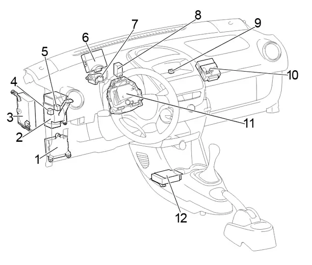
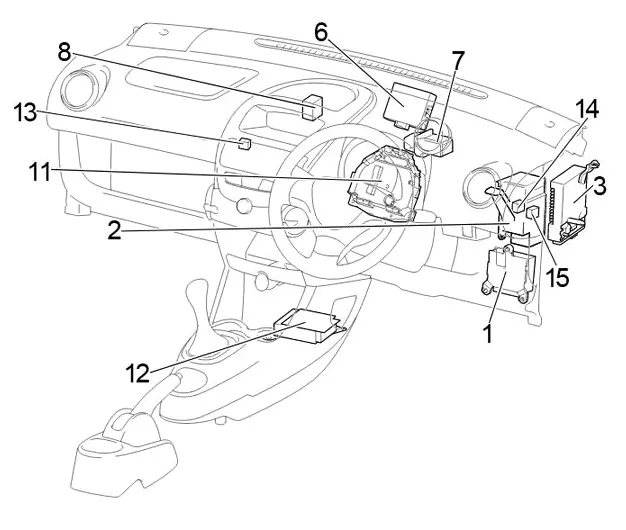
Description
- Power steering ECU
- Central connector
- ECU of multi-mode manual transmission
- Electric window relay
- LHD:
Before Feb 2012: Tail Light Relay
Since Feb 2012: Rear Fog Light Relay. - Door control system ECU with receiver
- Relay Block #1
- Air conditioner booster
- LHD: Fog Light Relay
- LHD: Daytime Running Light Relay
- Fuse box
- Airbag Sensor Assembly Center
- RHD: Relay Block #2
- RHD:
Before Feb 2012: Ignition Relay (IG)
Since Feb 2012: Window Relay. - RHD:
Before Feb 2012: Electric Window Relay
Since Feb 2012: Rear Fog Light Relay.
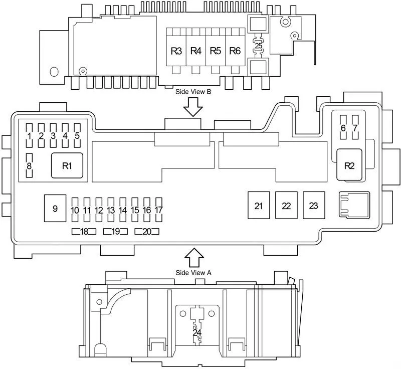
Fuse box
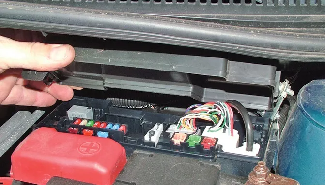
In the passenger compartment, the main fuse box is located on both sides of the speedometer, behind the protective box and consists of two parts.
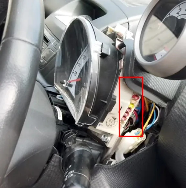
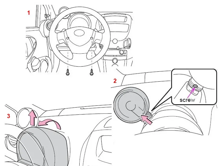
In order to remove the protective cover, you need to unscrew 3 screws. To do this, you will need to turn the steering wheel in different directions.
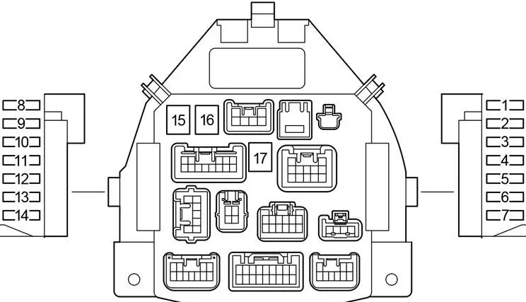
Designation
| 1 | 10A STOP – Brake lights, high mounted brake light, anti-lock brake system, multi-mode manual transmission |
| 2 | 25A D/L – Electric Door Lock System, Wireless Remote Control System |
| 3 | 20A DEF – Rear Window Defogger |
| 4 | 7.5A TAIL – Daytime running lights, tail lights, number plate light, side lights, headlight level control system, instrument panel lighting |
| 5 | 7.5A OBD – On-Board Diagnostics |
| 6 | 7.5A ECU-B – Multi-mode manual transmission, daytime running lights, vehicle stability control, gauges and instruments, rear fog light |
| 7 | – |
| 8 | 7.5A ECU-IG – Anti-lock braking system, vehicle stabilization system, electric power steering, electric cooling fan. |
| 9 | 10A BACK UP – Reversing lights, power door locks, wireless remote control, power windows, rear defogger, tachometer, air conditioning, heating system |
| 10 | 20A WIP – Windscreen Wiper and Washer, Rear Window Wiper and Washer |
| 11 | 15A ACC – Cigarette Lighter , Socket, Audio System |
| 12 | 7.5A IG1 – Windshield wiper and washer, rear window wiper and washer, anti-lock brake system, electric power steering system, electric cooling fan, reversing lights, power door lock system, wireless remote control system, power windows, rear window defogger, tachometer, air conditioning system, heating system |
| 13 | 15A IG2 – Multiport fuel injection system/sequential multiport fuel injection system, SRS airbag system, sensors and instruments, daytime running lights system, multi-mode manual transmission |
| 14 | 7.5A A/C – Air conditioning system, electric heater |
| 15 | 40A AM1 – Fuses “ACC”, “WIP”, “ECU-IG”, “BACK UP” |
| 16 | 30A PWR – Electric windows |
| 17 | 40A HTR – Heating System, Air Conditioning System, “A/C” Fuse |
Fuse number 11 for 15A is responsible for the operation of the cigarette lighter.
Relay Block #1
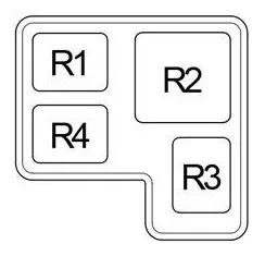
- R1 Accessory (ACC)
- R2 Heater (HTR)
- R3 Rear window heating (DEF)
- R4 LHD: Ignition (IG)
Relay Block #2
Scheme
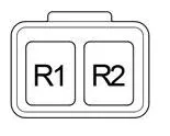
- R1 Ignition (IG)
- R2 Fog light (FOG)
Blocks under the hood
Location
General scheme
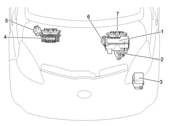
- Fuse and relay box
- Anti-skid control unit with drive
- Relay block
- LHD: Engine ECU
- LHD: glow plug relay
- RHD: Glow Plug Relay
- RHD: Engine ECU
Fuse and relay box
Under the hood, the fuse and relay box is located next to the battery and is covered with a protective cover.
| 1 | 15A EFI NO.4 – 2WZ-TV: Multiport fuel injection system / sequential multiport fuel injection system |
| 2 | 10A H-LP RH (HI) – Before February 2012: Right headlights. |
| 5A DRL – Since February 2012: daytime running lights. | |
| 3 | 10A H-LP LH (HI) – Before February 2012: Left headlamp, gauges and instruments. |
| 20A FR FOG – From February 2012: Front fog lights. | |
| 4 | 10A H-LP RH (LO) – Before Feb 2012: Right Headlights |
| 10A H-LP LH – From February 2012: Left headlight. | |
| 5 | 10A H-LP LH (LO) – Before February 2012: Left headlamp, gauges and instruments. |
| 10A H-LP RH – From February 2012: Right headlights. | |
| 6 | 7.5A STA – 1KR-FE: multi-mode manual transmission, multi-point fuel injection system / sequential multi-point fuel injection system. |
| 7.5A FAN NO.2 – 2WZ-TV: Electric cooling fan | |
| 7 | 7.5A EFI NO.2 – Multiport fuel injection system / sequential multiport fuel injection system, multi-mode manual transmission |
| 8 | 10A EFI NO.3 – 2WZ-TV: Multi-port fuel injection system / sequential multi-port fuel injection system, electric cooling fan. |
| 5A MET – Sensors and Counters | |
| 9 | 50A AMT – 1KR-FE: Multi-mode manual transmission. |
| 50A RADIATOR FAN – 2WZ-TV: Electric cooling fan | |
| 10 | 10A H-LP LH – without DRL: Left headlight |
| Before February 2012: 20A DIMMER – with DRL: fuses “H-LP LH (HI)”, “H-LP RH (HI)”, “H-LP LH (LO)”, “H-LP RH (LO)”, daytime running light system | |
| Since February 2012: 30A SUB-LP – with DRL: fuses “DRL”, “FOG FR” | |
| 11 | 30A VSC NO.2 – Anti-lock braking system and vehicle stability control system |
| 25A ABS NO.2 – without VSC: Anti-lock braking system | |
| 12 | 30A AM2 – Starting system, fuses “IG1”, “IG2”, “STA” |
| 13 | 10A HAZARD – Direction indicators, hazard warning lights, gauges and meters |
| 14 | 10A H-LP RH – Before February 2012: Right headlights. |
| 20A H-LP MAIN – Since February 2012: fuses “H-LP LH”, “H-LP RH”. | |
| 15 | 15A DOME – Gauges and meters, interior lighting, audio system, tachometer. |
| 16 | 15A EFI – 1KR-FE: Electric cooling fan, multiport fuel injection system / sequential multiport fuel injection system |
| 25A EFI – 2WZ-TV: Electric cooling fan, multi-port fuel injection system / sequential multi-port fuel injection system. | |
| 17 | 10A HORN – Signal |
| 18 | 7.5A Spare Fuse |
| 19 | 10A Spare Fuse |
| 20 | 15A Spare Fuse |
| 21 | 40A RADIATOR – Tropic: Electric Cooling Fan |
| 30A RADIATOR – Normal: Electric cooling fan | |
| 22 | 50A VSC NO.1 – Anti-lock braking system and vehicle stability control system |
| 40A ABS NO.1 – without VSC: Anti-lock braking system | |
| 23 | 50A EMPS – Electric Power Steering |
| 24 | 120A ALTERNATOR – 1KR-FE: Charging System, «EPS», «ABS (without vehicle stability control)», «VSC (with vehicle stability control)», «RADIATOR», «AM1», «HTR», «PWR», «D/L Fuses», «DEF», «TAIL», «STOP», «OBD», «ECU-B» |
| 25 | EBD resistor |
| Relay | |
| R1 | Air Conditioning Compressor Clutch (A/C MAG) |
| R2 | Starter (ST) |
| R3 | Engine Control Unit (EFI MAIN) |
| R4 | 1KR-FE: Fuel Pump (C/OPN) |
| R5 | Signal |
| R6 | Electric cooling fan (FAN #1) |
Relay block
Scheme
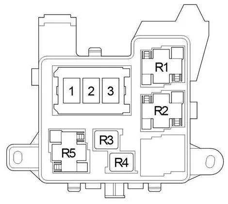
Designation
- 1 –
- 2 80A PTC2 – Heater
- 3 80A PTC1 – Heater
- R1 PTC heater relay (PTC1)
- R2 PTC heater relay (PTC2)
- R3 –
- R4 Before February 2012: Headlight (H-LP) / From February 2012: Daytime Running Lights (DRL).
- R5 Dimer (DIM)