The 2nd generation Skoda Octavia is based on the A5 platform . It was produced in 2004, 2005, 2006, 2007, 2008, 2009, 2010, 2011, 2012 and 2013 with station wagon and liftback bodies, with both petrol and diesel engines. In this article, we will provide a description of the fuse boxes and relays of the Skoda Octavia A5 (MK2) , their locations, photographs and diagrams. Separately, we will highlight the fuses responsible for the cigarette lighter and washer. In conclusion, we will offer a complete electrical diagram of the car for download.
The number of elements in the block and their purpose may differ from those shown and depend on the year of manufacture, vehicle equipment level and country of delivery.
Blocks in the cabin
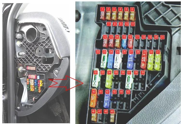
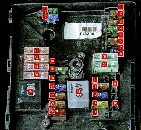
Fuse box
It is located at the end of the instrument panel behind a protective cover. On the back of which there should be an up-to-date description of the fuses in the form of a brochure.
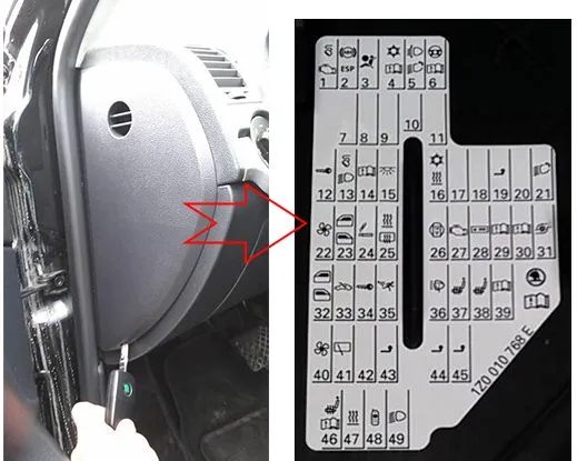
| No. | A | Description |
|---|---|---|
| 1 | 10A | Diagnostic connector, engine control unit, fuel pump |
| 2 | 5A | ABS, ESP control unit |
| 3 | 5A | Airbags |
| 4 | 5A | Heater, air conditioner, reversing light |
| 5 | 5A | Electric headlight corrector |
| 6 | 5A | Instrument cluster, automatic transmission control unit, electric power steering control unit, parking assistance system |
| 7 | Reserve | |
| 8 | Reserve | |
| 9 | Reserve | |
| 10 | Reserve | |
| 11 | Reserve | |
| 12 | 10A | Central locking control unit |
| 13 | 10A | External lighting control unit, brake lights |
| 14 | 5A | Automatic transmission control unit, gear selector lock |
| 15 | 7.5A | Interior Lighting Control Unit |
| 16 | 10A | Climate control system |
| 17 | Additional equipment | |
| 18 | 5A | Parking assistance system sensors |
| 19 | 5A | Towing hitch control unit |
| 20 | 5A | Hill Start Assist |
| 21 | Reserve | |
| 22 | 40A | Climate control fan |
| 23 | 30A | Front window lift |
| 24 | 15A | cigarette lighter fuse |
| 25 | 25/ 30A | Rear window heating. Additional heater |
| 26 | 20A | Power socket in the trunk |
| 27 | 15A | Fuel pump relay, fuel injectors |
| 28 | Additional equipment | |
| 29 | 10A | Engine control unit |
| 30 | 20A | Automatic transmission control unit |
| 31 | 20A | Brake system vacuum pump |
| 32 | 30A | Rear door window lifts |
| 33 | 25A | Electric sunroof |
| 34 | 20A | Comfort function control unit |
| 35 | 5A | Anti-theft system |
| 36 | 20A | Headlight washers |
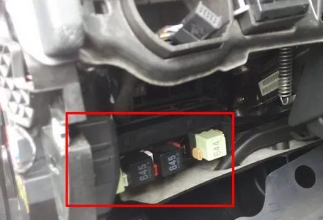
| 37 | 20A | Heated front seats |
| 38 | 30A | Rear seat heating |
| 39 | Reserve | |
| 40 | 40A | Heating system fan |
| 41 | 15A | Rear door window wiper |
| 42 | 15A | Windscreen washer |
| 43 | 15A | Towing hitch |
| 44 | 20A | Towing hitch |
| 45 | 15A | Towing hitch |
| 46 | 5A | Heating of windshield washer jets |
| 47 | 5A | Additional heater relay |
| 48 | Reserve | |
| 49 | 5A | Central light switch |
The fuse number 24 for 15A is responsible for the cigarette lighter. And for the windshield washer, number 42, also rated at 15A.
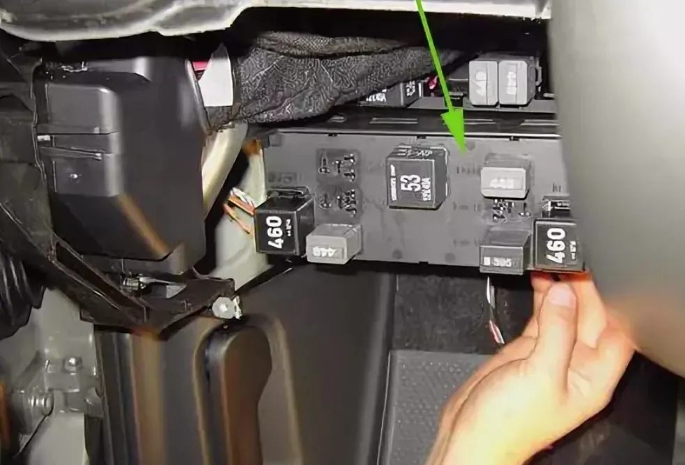
Relay block
It is located under the instrument panel itself, behind the trim panel.
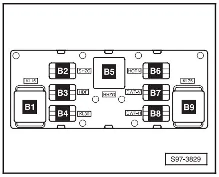
| No. | Designation |
|---|---|
| B4 | supply voltage relay (30) |
| B5 | rear window heating relay |
| B6 | horn relay |
| B7 | relay -1- windshield washer pump |
| B8 | relay -2- windshield washer pump |
| B9 | switching relay for contact X |
In this version, the central control unit is also located here.
Relay block under the central control unit
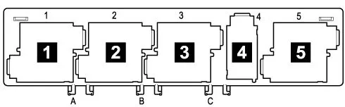
| No. | Purpose |
|---|---|
| 1 | Supply voltage relay (15) -J329- |
| 2 | Rear window heating device relay -J9- |
| 3 | supply voltage relay (50) -J682- / starter relay 1 -J906- |
| 4 | Fuel pump relay (pressure generation in the fuel system) -J643- (for engine letter designations BUD, CGGA, BSE, BSF, CMXA, CHGA) / fuel pump relay -J17- (for diesel engines) |
| 5 | switching relay for contact X -J59- |
| No. | Purpose |
|---|---|
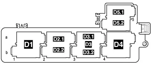
| D1 | Independent heater relay -J485- (for vehicles with independent additional heater) / relay for low heating output -J359- (for vehicles with resistive additional heater (RIH)) |
| D2.1 | Horn relay -J4- |
| D2.2 | fuel pump relay (for engine letter designations BUD, CGGA, BSE, BSF, CMXA, CHGA) / — additional fuel pump relay -J832- (for engine letter designations CLCA, CLCB, CFHF, CFHC, CEGA) |
| D3 | Relay for high heating capacity -J360- (for vehicles with additional resistive heater (RTS)) |
| D3.1 | Fresh air intake fan relay -J13- (for vehicles with independent auxiliary heater) |
| D3.2 | Additional heater fuel pump relay -J749- (for vehicles with independent additional heater) |
| D4 | starter relay 2 -J907- |
| D5.1 | Headlight washer relay -J39- |
| D5.2 | Relay for heating element -J925- (for engine code CAYC) |
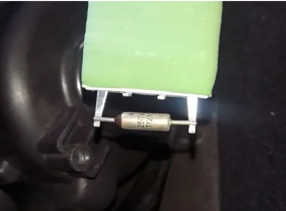
The stove does not work? Some models have a separate thermal fuse for the stove.
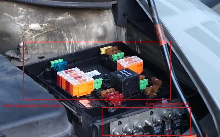
Block under the hood
It is located on the left side of the engine compartment under the protective cover and consists of 2 blocks:
- fuse and relay department
- department of high-power fuses in the form of fusible links
| No. | A | Purpose of fuses |
|---|---|---|
| 1 | Reserve | |
| 2 | 5A | Steering column switches |
| 3 | 5A | Diagnostic connector |
| 4 | 30A | ABS hydro-electronic module |
| 5 | 15A | Automatic transmission control unit |
| 6 | 5A | Instrument cluster |
| 7 | Reserve | |
| 8 | 15A | Audio system |
| 9 | 5A | Telephone |
| 10 | 5A | Power supply of the engine control unit relay |
| 11 | 20A | Additional heater and ventilation control unit |
| 12 | 5A | Information bus control unit |
| 13 | 15A | Engine control unit |
| 14 | 20A | Ignition |
| 15 | 5/ 15A | Oxygen sensor, fuel pump relay, glow plug relay |
| 16 | 30A | ABS control unit |
| 17 | 15A | Sound signal |
| 18 | 30A | Sound amplifier |
| 19 | 30A | Windscreen wipers |
| 20 | Reserve | |
| 21 | 15A | Oxygen concentration sensor |
| 22 | 5A | Clutch brake pedal switch |
| 23 | 5/ 10/ 15A | Additional air pump, high pressure fuel pump, mass air flow sensor |
| 24 | 10A | Exhaust gas recirculation valve |
| 25 | 30A | Right headlight |
| 26 | 30A | Left headlight |
| 27 | 40A | Additional air pump, preheating |
| 28 | 40A | Starter |
| 29 | 50A | Power supply clamp 30 |
| 30 | 50A | Terminal X – Equipment connected to this terminal is automatically switched on when the engine is started. |
| Relay | ||
| R1 | Radiator Fan Motor Relay | |
| R2 | Automatic transmission control relay | |
| R3 | supply voltage relay (15) | |