Mercedes-Benz Sprinter 906 represents the 2nd generation of the Mercedes Sprinter model range. Years of production: 2006, 2007, 2008, 2009, 2010, 2011, 2012, 2013, 2014, 2015, 2016 and 2017 with different engine options (411, 511, 515 CDI, etc.). In this material you will find information about the locations of electronic control units, a description of fuses and relays of the Mercedes Sprinter 906 with block diagrams and photo examples of their execution. We will highlight the fuses responsible for the cigarette lighter.

The design of the blocks and the purpose of their elements may differ from those presented and depend on the year of manufacture, equipment level and delivery region.
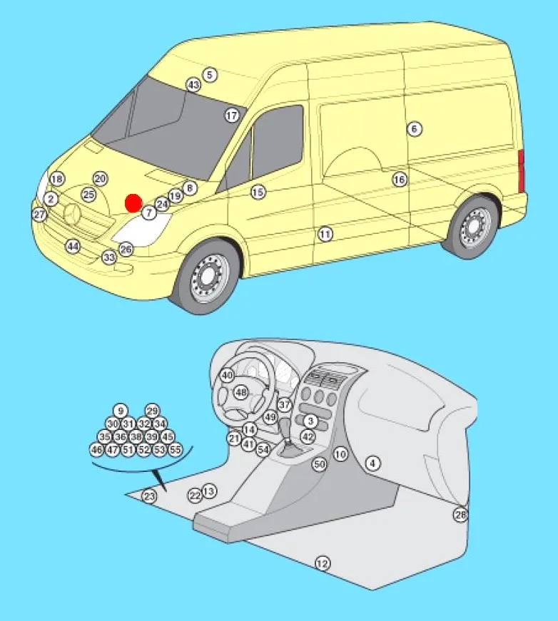
Block arrangement
General block layout diagram
| № | Description |
|---|---|
| 1 | ABS electronic control unit |
| 2 | Air conditioner condenser fan motor relay |
| 3 | Electronic air conditioning control unit – in the heater control panel |
| 4 | Air conditioner/heater fan motor control unit – next to the fan motor |
| 5 | Antenna signal amplifier |
| 6 | Air suspension control unit – strut “0” |
| 7 | Anti-theft system siren – engine compartment, left side |
| 8 | Additional battery – engine compartment, left side |
| 9 | Auxiliary battery relay |
| 10 | Auxiliary heater control unit (type 1) |
| 11 | Auxiliary heater control unit (type 2) |
| 12 | Auxiliary heater control unit (type C) – in the heater unit |
| 13 | Rechargeable battery |
| 14 | Diagnostic Connector (DLC) |
| 15 | Door electrical control unit, driver’s side |
| 16 | Left rear door electrical control unit |
| 17 | Right rear door electrical control unit |
| 18 | Electronic engine control unit (diesel) – engine 651 |
| 19 | Electronic engine control unit (diesel) – except engine 651 |
| 20 | Electronic engine control unit (petrol) – on the engine |
| 21 | Fuse/relay block, dashboard |
| 22 | Fuse/relay block, footwell |
| 23 | Fuse/relay block, under seat |
| 24 | Glow plug control unit – engine 646 |
| 25 | Glow plug control unit – except engine 646 |
| 26 | Headlight control unit, left (xenon headlights) |
| 27 | Headlight control unit, right (xenon headlights) |
| 28 | Headlight leveling control unit – A-pillar |
| 29 | Rear window heater relay 1 |
| 30 | Rear window heater relay 2 (with anti-theft system) |
| 31 | Windshield heater relay |
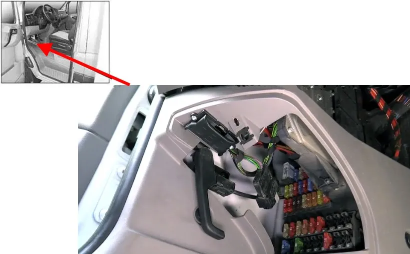
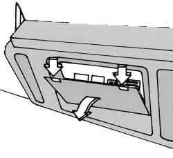
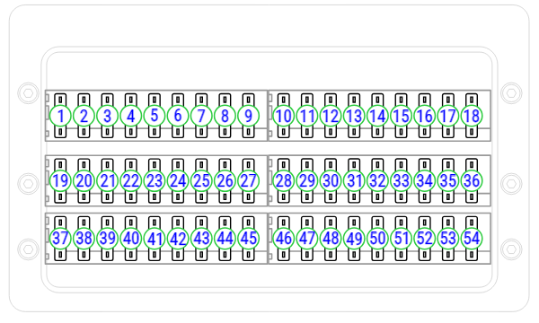
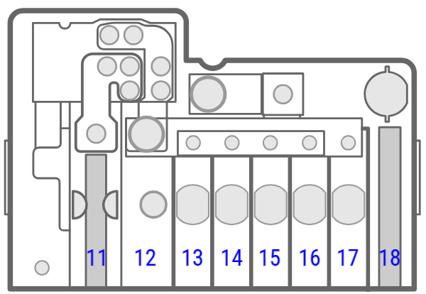
Fuse and relay block under the panel
Under the dashboard, in the footwell on the left side of the car, behind a protective cover, is the main fuse and relay box. To access it, you need to turn the bracket in the middle of the cover.
| № | A | Marking |
|---|---|---|
| 1 | 15A | Sound signal |
| 2 | 25A | Steering column lock (ELV), electronic ignition and starter switch (EZS) |
| 3 | 10A | Terminal 30z (petrol engines), electronic ignition and starter switch (EZS), instrument cluster |
| 4 | 5A | Light switch (LDS), switch block in the center console (OBF; terminal 30) |
| 5 | 30A | Front wiper |
| 6 | 15A | Fuel pump |
| 10A | Engine control, terminal 87 (5) (vehicles with code MI6/XM0) | |
| 7 | 5A | Steering Column Pipe Module (MRM) |
| 8 | 20A | Engine control, terminal 87 (2) |
| 9 | 20A | Engine control, terminal 87 (3) (vehicles with petrol engine) |
| 25A | Engine control, terminal 87 (3) (diesel vehicles) | |
| 20A | Engine control, terminal 87 (1) (vehicles with code MI6/XM0) | |
| 10 | 10A | Engine control, terminal 87 (4) |
| 11 | 15A | Terminal 15R |
| 12 | 10A | Airbag, terminal 15R |
| 13 | 15A | Audio module, cigarette lighter , glove box lighting, body manufacturer’s tailgate, PND (mobile navigation system) power socket |
| 14 | 5A | Light switch (LDS), instrument cluster, diagnostic connector, reversing light deactivation, anti-theft system with vehicle tracking, terminal 15 |
| 15 | 5A | Headlight range adjustment system (LWR), heating system in the front of the vehicle |
| 16 | 10A | Engine control, terminal 87 (1) |
| 17 | 10A | Airbag |
| 18 | 7.5A | Terminal 15, brake light switch |
| 19 | 7.5A | Interior lighting, terminal 30 |
| 20 | 25A | Terminal 30, right front window regulator, signal registration and excitation module |
| 21 | 5A | Engine control unit, terminal 15 |
| 22 | 5A | ABS, ESP, terminal 15 |
| 23 | 20/25A | Starter, terminal 50 |
| 10A | Engine control, terminal 87 (6) (vehicles with code MI6/XM0) | |
| 24 | 10A | Engine components, terminal 15 (diesel engines), control unit (vehicles with natural gas engine NGT) |
| 25 | 25A | Front panel socket |
| 26 | 25A | Driver’s door control unit |
| 27 | 10A | Diagnostic connector |
| 28 | 25A | Brake system (valves) |
| 29 | 40A | Brake system (priming pump) |
| 30 | 7,5/10A | Terminal 87 (5) engines (7.5A – M272, OM651; 10A – OM642) |
| 31 | 7,5/10A | Terminal 87 (6) engines (7.5A – OM651, M271, M272; 10A – OM642) |
| 32 | 30A | Faro cleaner |
| 33 | 15A | Anti-theft alarm system (EDW), flashing beacon/SGU |
| 34 | 10A | Reserve (until 03/07) |
| 10A | Additional turn signal module | |
| 35 | 15A | 1 DIN radio receiver |
| 20A | 2 DIN radio receiver | |
| 36 | 7.5A | Mobile phone, tachograph, navigation system holder |
| 37 | 30A | Front passenger compartment fan, auxiliary heating system, fan level 1 |
| 38 | 7.5A | Additional heating timer, radio, electrical equipment for retrofitting – DIN socket, FleetBoard system, anti-theft device with vehicle tracking |
| 39 | 30A | Seat heating |
| 40 | 10A | Body electrical equipment, third-party manufacturers |
| 5A | Brake system control unit | |
| 41 | 10A | Front air conditioning, CD changer, heating system, rear passenger compartment heating system |
| 42 | 7,5/10A | Motion sensor, comfort lighting, satellite radio, reading lamp and cargo area light, luggage compartment light |
| 43 | 7.5A | Air conditioning in the rear of the cabin |
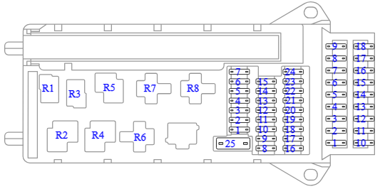
| Relay | ||
| R1 | Horn relay | |
| R2 | Front wiper relay, mode 2 | |
| Wiper relay, stage 1/2 | ||
| R3 | Fuel pump relay | |
| Starter relay, terminal 15 (vehicles with code MI6/XM0) | ||
| R4 | Front wiper relay, mode 1 | |
| Wiper on/off relay | ||
| R5 | Starter relay, terminal 50 | |
| R6 | Relay, terminal 15R | |
| R7 | Engine control relay, terminal 87 | |
| R8 | Relay, terminal 15 | |
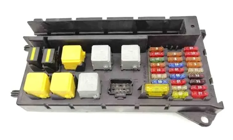
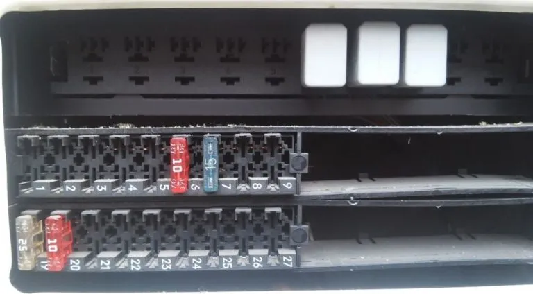
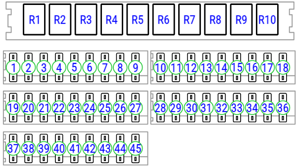
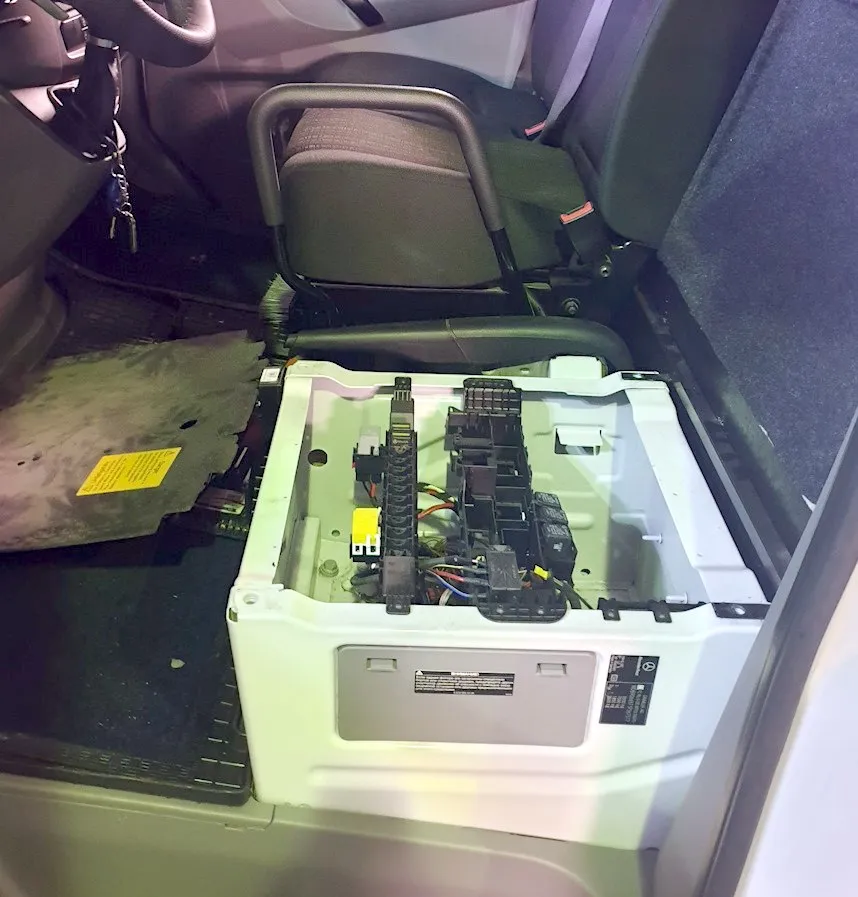
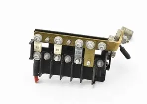
Fuse and relay blocks under the seat
On the left side, under the driver’s seat, there are several blocks with fuses and relays.
Fuse and relay box on the side of the seat
To access it, you must remove the protective cover.
Option 1
| № | A | Appointment |
|---|---|---|
| 1 | 5A | Mirror adjustment, rear window heating relay |
| 2 | 30A | Rear wiper |
| 3 | 5A | Heater timer, reversing camera, neutral switch (with traction control, all-wheel drive and engine run-on function), electrical equipment for retrofitting – DIN socket (roof), FleetBoard system, anti-theft system with vehicle tracking, emergency hammer lighting in the rear of the vehicle, emergency exit lighting |
| 4 | 7.5A | Tachograph, Automatic Speed Regulation (ADR), Power Take-Off, Trailer Hitch (AAG) |
| 5 | 10A | Gear shift system control unit (EGS), terminal 87 |
| 5A | Start function, ECO engine shutdown, hood switch | |
| 6 | 5A | All-wheel drive |
| 10A | All-wheel drive, ground clearance adjustment system (ENR), additional oil pump | |
| 7 | 7,5/10/15A | Automatic transmission control lever module (EWM) |
| 8 | 10A | Three-way tipper/tailgate, terminal 15, PARKTRONIC |
| 9 | 15A | SGU/roof fan |
| 7.5A | Air conditioning compressor clutch, warning buzzer for reversing alarm, which is switched off | |
| 10 | 25A | Body equipment, terminal 30 |
| 11 | 15A | Body equipment, terminal 15 |
| 12 | 10A | Body equipment, terminal D+ |
| 13 | 10A | Additional turn signal indicator module (up to 03/07) |
| 30A | Air conditioning in the rear of the cabin | |
| 20A | Fuel pump FSCM (Fuel Level Control Module) | |
| 15A | Fuel pump relay without FSCM (vehicles with code MI6/XM0) | |
| 14 | 20A | Trailer socket |
| 15 | 25A | Trailer coupling device (AAG) |
| 16 | 7.5A | Tire pressure monitoring system (RDK), Parktronic |
| 17 | 25A | Parameterized Special Module (PSM) Control Unit |
| 18 | 25A | Parameterized Special Module (PSM) Control Unit |
| 19 | 5/10A | Ceiling-mounted control panel (DBE) |
| 25A | Lift-and-slide sunroof, ceiling-mounted control panel (DBE) | |
| 10A | EPA-GLONASS system | |
| 20 | 7.5A | Marker lights, license plate lights, identification light |
| 21 | 30A | Heated rear window without EDW (anti-theft alarm system) |
| 15A | Heated rear window with EDW (anti-theft alarm system) | |
| 22 | 15A | Heated rear window |
| 20A | Car power socket | |
| 23 | 10A | Body electrical equipment, third-party manufacturer |
| 15A | Socket in the rear of the cabin, left | |
| 24 | 15A | Driver’s seat box socket |
| 25 | 15A | Socket in the rear of the cabin on the right |
| 26 | 25A | Additional liquid heater |
| 27 | 25A | Additional heater |
| 20A | Additional air heater | |
| 28 | 30A | Air conditioning in the rear of the cabin (until 03/07) |
| 7.5A | CNG, terminal 87 | |
| 25A | Starter relay SRB (fuse and relay block; vehicles without buffer battery) | |
| 25A | Starter with support from the on-board network via an additional battery | |
| 29 | 10/30A | All-wheel drive |
| 7.5A | Terminal 87 (7) gas fuel system, vehicles with natural gas engine NGT | |
| 30 | 30A | Air suspension (compressor), brake booster (for North American countries) |
| 10A | All-wheel drive (compressor) | |
| 15A | Additional heat exchanger fan | |
| 31 | 15/30A | Sliding door on the left, fan in the rear of the cabin |
| 15A | Sliding door closing mechanism booster, left | |
| 32 | 10A | Keyless Entry |
| 5A | SCR system – exhaust gas aftertreatment system control relay | |
| 33 | 30A | Sliding door right, suspension unit (ENR) |
| 15A | Sliding door closing mechanism booster, right | |
| 34 | 30A | Left sliding door (until 03/07) |
| 20A | SCR system – heating system 1, AdBlue® reductant, vehicles with diesel exhaust gas aftertreatment system | |
| 35 | 30A | Brake booster |
| 5A | SCR system – heating system 2, AdBlue® reductant, vehicles with diesel exhaust gas aftertreatment system | |
| 36 | 15A | SCR system – control and heating system 3, AdBlue® reductant, vehicles with diesel exhaust gas aftertreatment system |
| 37 | 5A | COLLISION PREVENTION ASSIST / FCW (Forward Collision Warning) |
| 5A | Rebuilding alarm / BSM (dead zone monitoring system) | |
| 38 | 10A | Multifunctional video camera (MK) with adaptive high beam headlights with lane departure warning function |
| 39 | 7.5A | Body electrical equipment (delivery operation), reinforced air conditioning system in the rear of the vehicle |
| 15A | Ceiling fan, siren | |
| 40 | 15A | Charging current from the buffer battery (vehicles with a buffer battery) |
| 41 | 7.5A | SAM (signal acquisition and excitation module) reference voltage of the buffer battery |
| 42 | 30A | Air conditioning system in the rear of the car |
| 43 | 10A | Electric step/sliding door, right |
| 44 | 10A | Electric step/sliding door, left |
| 45 | 5A | Electric step, control module and warning buzzer |
| Relay | ||
| R1 | Relay class D+ of the body manufacturer | |
| R2 | Relay cl. 15 body manufacturer | |
| R3 | Lighting relay | |
| Tail lift relay | ||
| R4 | Headlight relay | |
| R5 | Flashing beacon relay | |
| R6 | EDW sound signal relay (EDW – anti-theft alarm system) | |
| R7 | Not used | |
| R8 | SGU relay | |
| R9 | Circulation pump relay | |
| R10 | Not used | |
Option 2
| № | A | Description |
|---|---|---|
| 1 | 5A | Driver’s door power window control panel Rear window heating relay 2 |
| 2 | 30A | Rear window wiper motor in the swing doors |
| 3 | 5A | Timer Neutral switch Gearbox Display panel Rear view camera |
| 4 | 7.5A | Switch for adjusting the operating speed PTO control sensor Trailer recognition control unit Tachograph control unit |
| 5 | 5/10A | Selector Electronically controlled manual transmission control unit Bonnet limit switch (from November 2011) |
| 6 | 5/10A | Crankcase ventilation system heater Battery regulation system control unit (from May 2011 to May 2013) |
| 7 | 10A | Fuel filter heating element |
| 8 | 5/10A | Tilt button Parking assistant control unit (from May 2013) Special body relay, cl. 15 (until November 2011) 6-pin connector -T6ah- 7-pin connector -T7f- (tailgate connector block) |
| 9 | 15A | Roof fan switch for cargo compartment supply ventilation (until November 2011) Siren relay (until November 2011) Not used (since November 2011) |
| 10 | 25A | For the manufacturer of superstructures and special equipment |
| 11 | 15A | Relay for special add-ons, class 15 |
| 12 | 10A | Relay of special super-boosts, class 61 |
| 13 | Reserve | |
| 14 | 20A | Connector, 9-pin -T9b- (preparation for retrofitting of fuel injection system) TSU socket |
| 15 | 25A | Trailer recognition control unit |
| 16 | 7.5A | Parking assistant control unit Tire pressure monitoring system control unit |
| 17 | 25A | Control unit for programmable special functions |
| 18 | 25A | Control unit for programmable special functions |
| 19 | 5/25A | Roof electrical control unit |
| 20 | 7.5/10A | Coolant pump relay after engine shutdown Entrance and footwell lighting relay |
| 21 | 30A | Rear window heating relay |
| 22 | 15A | Rear window heating relay 2 |
| 23 | 10/15A | Cargo platform lighting switch 12 V socket 2 -U18- |
| 24 | 15A | 12 V socket 4 |
| 25 | 15A | 12 V socket 3 |
| 26 | 25A | Auxiliary heater control unit |
| 27 | 20/25A | Auxiliary heater control unit |
| 28 | 30/40A | Transmission hydraulic pump relay, Starter relay 1 |
| 29 | 15A | Electronically controlled manual transmission control unit |
| 30 | 5A | Battery regulation system control unit |
| 31 | 15/30A | Left sliding door control unit (from May 2012) Rear supply fan control unit Rear supply fan |
| 32 | 5A | Control unit for battery monitoring |
| 33 | 7.5/15/30A | Not used Right sliding door control unit (from May 2012) Transfer case lock relay (from January 2012) Air compressor (from January 2012) |
| 34 | 7.5/15A | Reductant heating system control unit Gearbox sensor for differential lock |
| 35 | 3/15A | Reductant heating system control unit Air compressor protection control unit (since January 2012) |
| 36 | 5A | Not used (until January 2012) Air compressor switch (since January 2012) |
| 37 | Reserve | |
| 38 | Reserve | |
| 39 | 7.5/15A | Roof fan switch for cargo compartment supply ventilation (from November 2011) Siren relay (from November 2011) |
| 40 | Reserve | |
| 41 | Reserve | |
| 42 | 30A | Evaporator fan control unit -J349- |
| 43 | Reserve | |
| 44 | Reserve | |
| 45 | Reserve | |
| 46 | Reserve | |
| 47 | Reserve | |
| 48 | Reserve | |
| 49 | Reserve | |
| 50 | Reserve | |
| 51 | Reserve | |
| 52 | Reserve | |
| 53 | Reserve | |
| 54 | Reserve | |
| 55 | Reserve | |
| 56 | Reserve |
Relay under the seat
Additional relays can be installed under the seat itself.
| № | Description |
|---|---|
| R1 | Starter relay, right-hand drive vehicles |
| R2 | Unloading relay, terminal 15 |
| R3 | Relay, terminal 15, starter |
| R4 | Secondary air injection/secondary air pump relay SCR system relay, vehicles with exhaust gas aftertreatment system |
| R5 | Fuel pump relay |
| R6 | Front fan relay, fan speed 1 |
| R7 | Unloading relay, terminal 15 R |
| R8 | Starter relay, auxiliary battery Starter relay, left-hand drive vehicles |
| R9 | Relay 1, rear window heating system |
| R10 | Relay 2 for rear window heating with EDW (anti-theft alarm system) Relay for snow plow, low beam on the left |
| R11 | Relay 1, electric step left Snow plow relay, low beam right |
| R12 | Relay 2, electric footrest left Snow plow relay, high beam left |
| R13 | Unloading relay, terminal 15 (2) Snow plow relay, high beam right |
| R14 | Relay 1, windshield heating system |
| R15 | Relay, body manufacturer, terminal 15 |
| R16 | Relay, body manufacturer, terminal 61 (D+) |
| R17 | Equipment relay for retrofitting with a tail lift Comfort lighting relay |
| R18 | Headlight cleaner relay |
| R19 | Beacon relay with siren |
| R20 | EDW system relay (anti-theft alarm system), sound signal |
| R21 | Relay for contour/identification lights (for North American countries) Relay for license plate lights (delivery operation) Relay for fan, additional air heating, fan level 1 |
| R22 | Fan relay, additional air heating, fan level 2 |
| R23 | Beacon relay with siren Relay, terminal 61 (D+), anti-theft device with vehicle tracking |
| R24 | Relay 1, electric footrest right |
| R25 | Relay 2, electric footrest right |
| R26 | Reverse alarm relay off Anti-theft device relay with vehicle tracking |
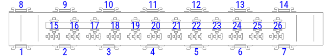
Power fuse block
If an additional battery is installed under the seat, an additional high-power fuse block can also be installed.
| № | A | Appointment |
|---|---|---|
| 1 | Reserve | |
| 2 | 80A | Signal Acquisition and Excitation Module (SAM) / Fuse and Relay Module (SRB) |
| 3 | Reserve | |
| 4 | 150A | Buffer battery input |
| 5 | 150A | SAM (Signal Acquisition and Excitation Module) / SRB (Fuse and Relay Block), terminal 30 fuse block |
| 6 | ||
| 7 | ||
| 8 | 100A | Brake – retarder, combined with battery disconnector relay |
| 9 | 150A | Additional battery |
| 10 | 250A | Hydraulic pump for driving snow plow, Tail lift, Dump truck |
| № | A | Description |
|---|---|---|
| 12 | Reserve | |
| 13 | 150A | Electric additional heating device (PTC) |
| 80A | Air conditioning system in the rear of the car, reinforced | |
| 14 | 60A | Air conditioning electric fan – cabin without partition or with reinforced air conditioning system in the rear of the vehicle (vehicles with a wheelbase of 3665 mm) |
| 40A | Air conditioning fan – cabin with partition or with reinforced air conditioning system in the rear of the vehicle | |
| 40A | Air conditioning fan – cabin, open car modification | |
| 70A | Electric fan | |
| 15 | Reserve | |
| 16 | 100A | Retarder, not in combination with battery disconnect relay |
| 150A | Battery disconnector relay | |
| 17 | Reserve | |
| 18 | 300A | Generator |
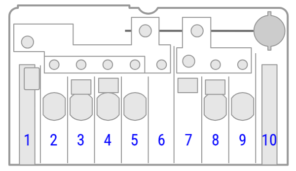
Battery-powered unit
The power fuse block in the form of fuse links is located near the battery in the footwell on the left side of the vehicle.

| № | A | Marking |
|---|---|---|
| 1 | 80A | Engine preheating relay |
| 40A | Secondary air pump (cars with gasoline engine) | |
| 2 | 80A | Engine cooling system fan – air conditioning |
| 25A | Relay, terminal 15, starter (vehicles with code MI6/XM0; vehicles with buffer battery) | |
| 25A | Starter relay, unsupported (vehicles with buffer battery) | |
| 70A | Engine cooling fan (vehicles without buffer battery) | |
| 40A | Air conditioning fan – cabin (vehicles without buffer battery) | |
| 40A | Air conditioning fan – cabin with partition or with reinforced air conditioning system in the rear of the vehicle (vehicles without buffer battery) | |
| 60A | Air conditioning electric fan – cabin with partition or with reinforced air conditioning system in the rear of the vehicle (vehicles with a wheelbase of 3665 mm; vehicles without a buffer battery) | |
| 3 | 80A | Signal registration and excitation module / fuse and relay block (vehicles without buffer battery) |
| 4 | 150A | Additional battery in the engine compartment, retarder (vehicles without buffer battery) |
| 5 | 150A | Terminal 30, fuse blocks, signal recording and excitation module / fuse and relay block (vehicles without buffer battery) |
| 6 | Seat frame support point (jumper) | |
| 7 | 150A | Auxiliary heater (RTS) (vehicles without buffer battery) |
| 80A | Rear air conditioning system, reinforced (vehicles without buffer battery) |