Toyota Yaris 3rd generation was produced in 2011, 2012, 2013, 2014, 2015, 2016, 2017 and 2018 and was designated as P130 / P150. It was supplied worldwide. In some countries it is known under the names Toyota Echo, Toyota Vitz, Toyota Platz . In this article, we will show the location of all electronic control units, a description of fuses and relays of Toyota Yaris Vitz 3rd generation with block diagrams and their locations. We will highlight the fuse responsible for the cigarette lighter.

Blocks in the cabin
Location
General layout of the units in the cabin
Left hand drive
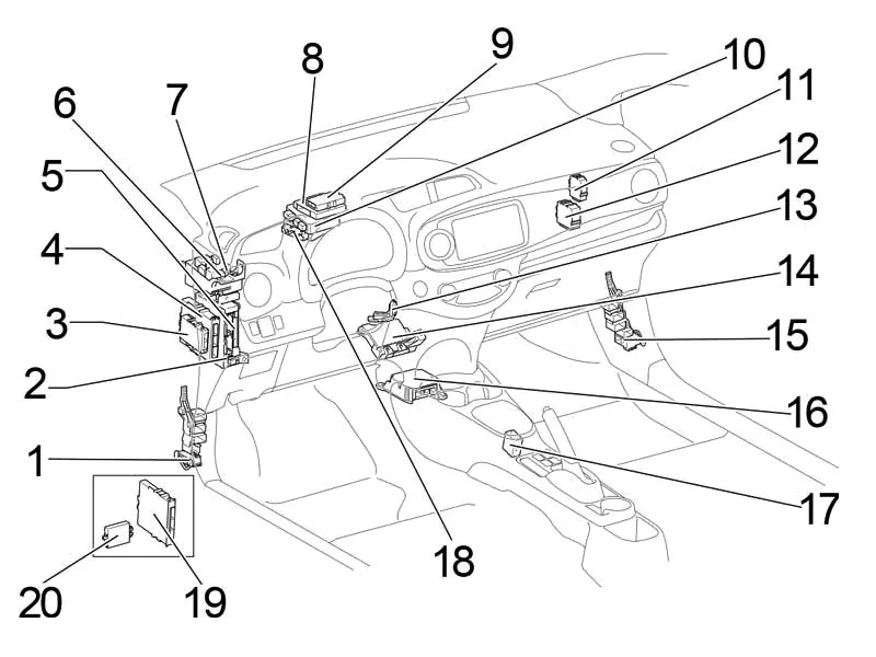
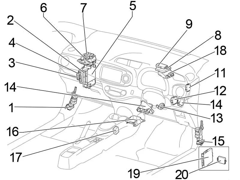
- Distribution block
- Fuse box
- Engine and gearbox control unit (without start-stop system)
- Start-stop system control unit
- Body electrical equipment control unit
- Heater relay (HTR)
- Relay block
- Driver assistance systems control unit
- Engine and gearbox control unit (with start-stop system)
- Gearbox Control Unit (LHD)
- Network Gateway Block
- Windscreen wiper relay
- Key transponder amplifier
- Air conditioner booster
- Distribution block
- Airbag control unit
- Gear selector lock control unit
- Power Steering Control Unit
- Certification Block
- ID Code Unit (with Smart Entry & Start System)
Transponder Key Control Unit (without Smart Entry & Start System)
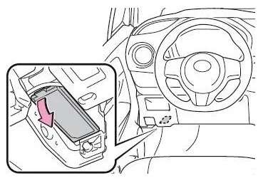
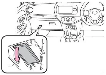
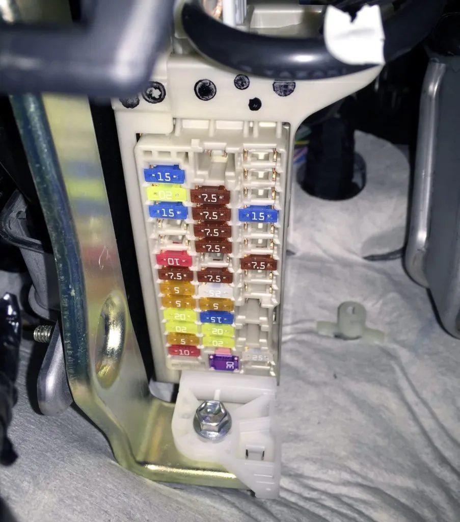
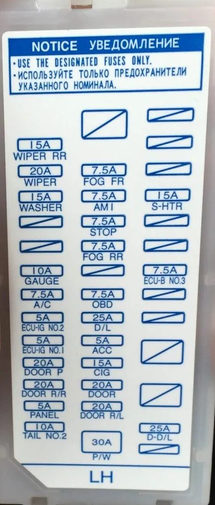
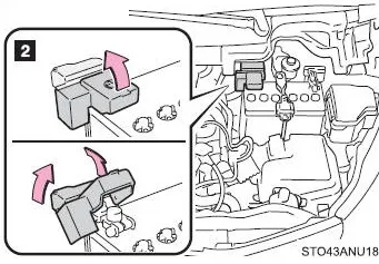
Fuse box
It is located under the instrument panel, covered with a protective cover.
Left hand drive
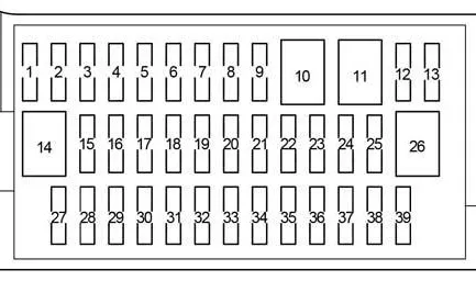
| 1 | – |
| 2 | – |
| 3 | – |
| 4 | 15A S-HTR – Heated Seats |
| 5 | – |
| 6 | – |
| 7 | 7.5A ECU-B NO.3 – Power Mirrors |
| 8 | – |
| 9 | – |
| 10 | – |
| 11 | – |
| 12 | 25A DD/L – Double Locking |
| 13 | – |
| 14 | – |
| 15 | 15A FOG FR – before June 2013: Front fog light |
| 15A FOG FR – from June 2013 (TMC): Front fog light (TMC – Toyota Motor Corporation) | |
| 7.5A FOG FR – since June 2013 (TMMF): Front fog light (TMMF – Toyota Motor Manufacturing France) | |
| 16 | 7.5A AM1 – Starting System |
| 17 | 7.5A STOP – Multiport fuel injection system / sequential multiport fuel injection system, VSC, brake light lamps, additional brake light |
| 18 | 7.5A FOG RR – Rear Fog Light |
| 19 | – |
| 20 | 7.5 OBD – Diagnostic connector |
| 21 | 25A D/L – Central locking, body electrical control unit |
| 22 | 5A ACC – Body electrical equipment control unit, electric mirrors, audio system, gear selector lock |
| 23 | 15A CIG – Socket (cigarette lighter) |
| 24 | 20A DOOR – Window lifters |
| 25 | 20A DOOR R/L – Window Lifters |
| 26 | 30A P/W – Window lifters |
| 27 | 15A WIPER RR – Rear Windscreen Wiper |
| 28 | 20A WIPER – Windscreen wiper |
| 29 | 15A WASHER – Glass washer |
| 30 | – |
| 31 | – |
| 32 | 10A GAUGE – Reverse Lights, Shift Lock, Audio, Charging System, Multiport Fuel Injection System/Sequential Multiport Fuel Injection System |
| 33 | 7.5A A/C – Air conditioning, heated rear window, heated mirrors |
| 34 | 5A ECU-IG NO.2 – VSC |
| 35 | 5A ECU-IG NO.1 – Cooling fan, rear window defogger, VSC, electric power steering, body electrical control unit, wireless control system, tire pressure monitoring system |
| 36 | 20A DOOR P – Window lifters |
| 37 | 20A DOOR R/R – Window lifters |
| 38 | 5A PANEL – Instrument cluster, instrument panel lighting, light switch |
| 39 | 10A TAIL NO.2 – Side light, number plate light |
Fuse number 23, 15A, is responsible for the operation of the cigarette lighter.
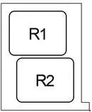
Relay block
Scheme
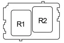
- R1 – Interior lighting (DOME CUT)
- R2 – up to July 2014: Front fog light (FR FOG) / from May 2015: (STP)
Additional elements
Scheme
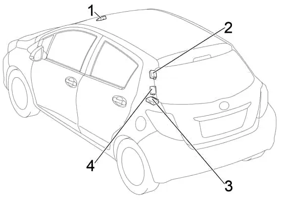
- Collision avoidance system sensor
- Tire pressure monitoring system receiver
- Audio amplifier
- Central lock receiver
Blocks under the hood
Location
General layout of the blocks under the hood
Left hand drive
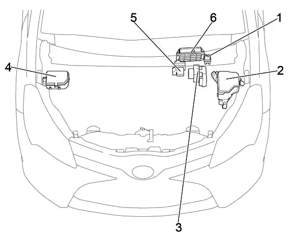
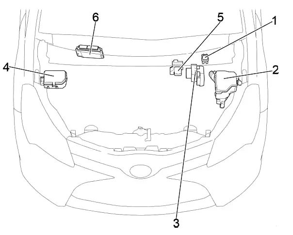
- Glow Plug Relay
- Fuse and relay box
- Brake control unit
- Fuse box #2
- Power fuse box
- Engine control unit
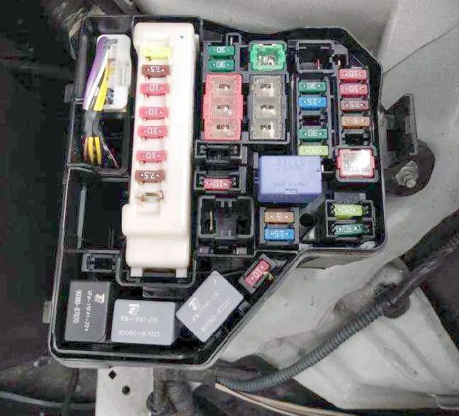
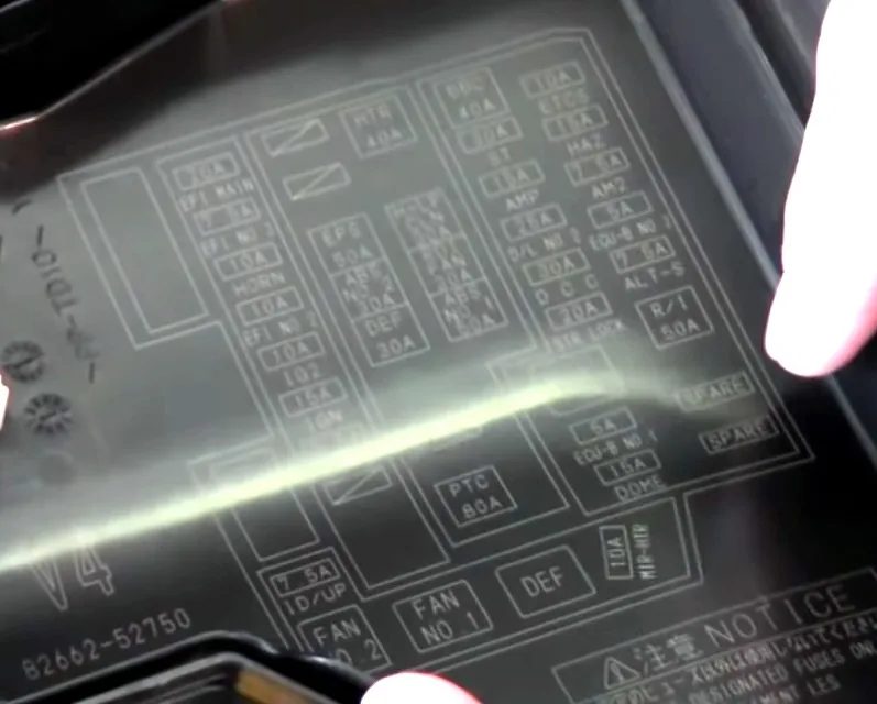
Fuse and relay box
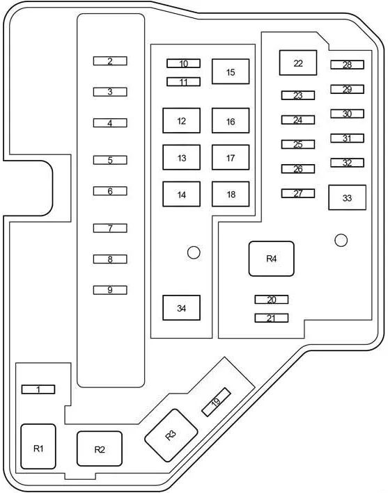
| 1 | 7.5A ID/UP – Multiport fuel injection system / sequential multiport fuel injection system |
| 2 | 20A EFI MAIN – Gasoline: Multiport fuel injection system / Sequential multiport fuel injection system |
| 30A ECD MAIN – Diesel: Multiport fuel injection system / sequential multiport fuel injection system | |
| 3 | 7.5A EFI NO.3 – Multiport fuel injection system/sequential multiport fuel injection system |
| 4 | 10A HORN – Horn |
| 5 | 10A EFI NO.2 – Multiport fuel injection system / sequential multiport fuel injection system |
| 6 | 10A IG2 – Multiport fuel injection system/sequential multiport fuel injection system, air bags, brake lights, front passenger classification system |
| 7 | 15A IGN – Multiport fuel injection system / sequential multiport fuel injection system |
| 8 | 7.5A MET – Instrument cluster |
| 9 | – |
| 10 | 30A PTC HTR NO.3 – from July 2014 (TMMF): Auxiliary heater (TMMF – Toyota Motor Manufacturing France) |
| 11 | 25A PWR HTR – before July 2014 (TMMF): Auxiliary heater (TMMF – Toyota Motor Manufacturing France) |
| 30A PTC HTR NO.2 – from July 2014 (TMMF): Auxiliary heater (TMMF – Toyota Motor Manufacturing France) | |
| 12 | 50A EPS – Electric Power Steering |
| 13 | 30A ABS NO.2 – ABS, VSC |
| 14 | 30A DEF – Rear window heating, mirror heating |
| 15 | 40A HTR – Air conditioning |
| 16 | 50A PTC HTR NO.1 – TMMF: Auxiliary Heater (TMMF – Toyota Motor Manufacturing France) |
| 30A H-LP CLN – Headlight Cleaner | |
| 17 | 30A RDI FAN – Cooling system fan |
| 18 | 50A ABS NO.1 – ABS, VSC |
| 19 | 10A MIR-HTR – Heated Mirrors, Heated Rear Window, Cruise Control, Gear Indicator, Engine Control Unit |
| 20 | 5A ECU-B NO.1 – Multiport fuel injection system / sequential multiport fuel injection system, body electrical control unit |
| 21 | 15A DOME – Interior lighting, personal lighting, audio system, VSC |
| 22 | 40A BBC – Charging system (1NR-FE), start-stop system |
| 23 | 30A ST – Starting System |
| 24 | 15A AMP – TMMF: Audio system, navigation, parking assistance system (TMMF – Toyota Motor Manufacturing France) |
| 25 | 25A D/L NO.2 – before July 2014: Double locking |
| 25A PWR HTR – up to July 2014 (TMMF): Auxiliary Heater (TMMF – Toyota Motor Manufacturing France) | |
| 26 | 30A DCC – Fuses: “DOME”, “ECU-B NO.1”, “ECU-B NO.2” |
| 27 | 20A STR LOCK – up to July 2014 (TMMF): Tailgate, Immobilizer, Intelligent Entry with Push Button Start, Start System, Steering Lock, Wireless Remote Control (TMMF – Toyota Motor Manufacturing France) |
| 28 | 10A ETCS – Multiport fuel injection system / sequential multiport fuel injection system |
| 29 | 10A HAZ – Direction indicators, hazard warning lights |
| 30 | 7.5A AM2 – Distributed fuel injection system / sequential distributed fuel injection system, starting system |
| 31 | 5A ECU-B NO.2 – Instrument cluster, wireless control system, tire pressure monitoring system, front passenger classification system |
| 32 | 7.5A ALT-S – Charging System |
| 33 | 50A R/I – Fuses: “EFI MAIN”, “EFI NO.2”, “EFI NO.3”, “IG2”, “IGN”, “MET”, “HORN” |
| 34 | 80A PTC – Auxiliary heater, heated mirrors |
| Relay | |
| R1 | Cooling system fan (FAN NO.2) |
| R2 | Cooling system fan (FAN NO.1) |
| R3 | Rear window heating (DEF) |
| R4 | Starter (ST) |
Fuse box #2
Scheme
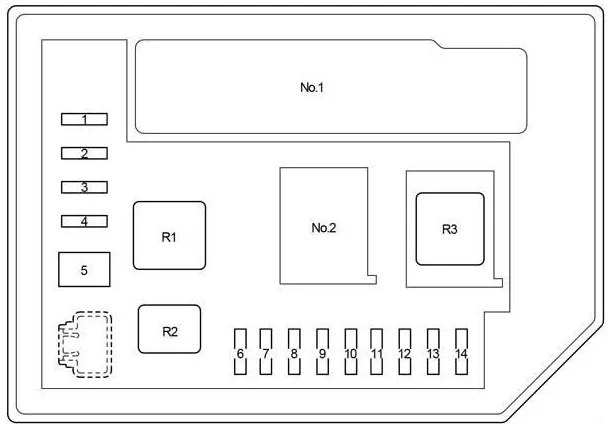
| 1 | 20A ST NO.2 – Multiport fuel injection system/sequential multiport fuel injection system |
| 2 | 7.5A DRL – Daytime Running Lights |
| 15A EU-DRL – Daytime Running Lights | |
| 3 | 10A ECD NO.4 – Cooling fan, multipoint fuel injection system/sequential multipoint fuel injection system |
| 10A S-HORN – Multiport fuel injection system/sequential multiport fuel injection system | |
| 4 | 7.5A H-LP MAIN – up to July 2014: Air conditioning, automatic lighting system, headlights, headlight range control |
| 20A H-LP MAIN – since July 2014: Air conditioning, automatic lighting system, headlights, headlight range control | |
| 5 | 50A MMT – Gearbox Control Unit |
| 6 | 10A H-LP RH HI – High beam right |
| 7 | 10A H-LP LH HI – Left high beam, instrument cluster |
| 8 | 10A H-LP RH LO – Low beam right |
| 9 | 10A H-LP LH LO – Low beam left, front fog light |
| 10 | – |
| 11 | – |
| 12 | – |
| 13 | – |
| 14 | – |
| Relay | |
| R1 | before July 2014: Dimmer (DIM) (headlight switch) |
| since July 2014: Auxiliary heater (PTC HTR NO.1) | |
| R2 | Daytime running lights/anti-theft alarm system (DRL/S-HORN) |
| R3 | Headlights (H-LP) |
| Headlights / Daytime Running Lights (H-LP/US-DRL) | |
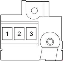
Department No. 1
Scheme
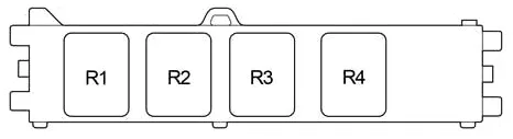
- R1 – Integrated relay
Since July 2014
| R1 | Engine Control Unit (ECD NO.2) |
| R2 | Auxiliary heater (PTC HTR NO.2) |
| R3 | Auxiliary heater (PTC HTR NO.3) |
| R4 | Starter (ST NO.2) |
Department No. 2
Scheme
R2 – (O/P MTR (with Stop & Start System)) or R1 – Gearbox Control Unit (MMT)
Since July 2014
R1 – Dimmer (DIM (Projector Headlight))
Power fuse box
Located on the positive terminal of the battery.
- 80A GLOW DC/DC – Multiport fuel injection system/sequential multiport fuel injection system
- 80A MAIN – Fuses: “BBC”, “ST”, “AMP”, “D/L NO.2”, “DCC”, “STR LOCK”, “MIR-HTR”, “ETCS”, “HAZ”, “AM2”, “ALT-S”, “R/I”, “DRL” “EU-DRL”, “S-HORN”, “H-LP MAIN”, “H-LP RH” HI”, “H-LP LH HI”, “H-LP RH LO”, “H-LP LH LO”
- ALT 120A – Charging system, Fuses: “ID/UP”, “EPS”, “ABS NO.2”, “DEF”, “PTC”, “HTR”, “H-LP CLN”, “RDI FAN”, “ABS NO.1”, “TAIL NO.2”, “PANEL”, “DOOR R/R”, “DOOR P”, “ECU-IG NO.1”, “ECU-IG” NO.2”, “A/C”, “GAUGE”, “WASHER”, “WIPER”, “WIPER RR”, “P/W”, “DOOR R/L”, “DOOR”, “CIG”, “ACC”, “D/L”, “OBD”, “STOP”, “AM1”, “FOG FR”