Volvo S80 1 generation was produced in 1998, 1999, 2000, 2001, 2002, 2003, 2004, 2005 and 2006 in the TS body. During this time, the model was updated. In this publication, you will find a description of the fuses and relays of the Volvo s80 with block diagrams, photo examples of their design and location. Let’s highlight the cigarette lighter fuse.

The purpose of fuses and relays may differ from that shown and depends on the year of manufacture, region of delivery and the level of electrical equipment of your car.
Blocks in the cabin
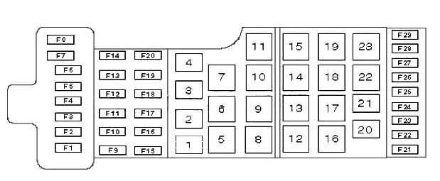
Fuse box
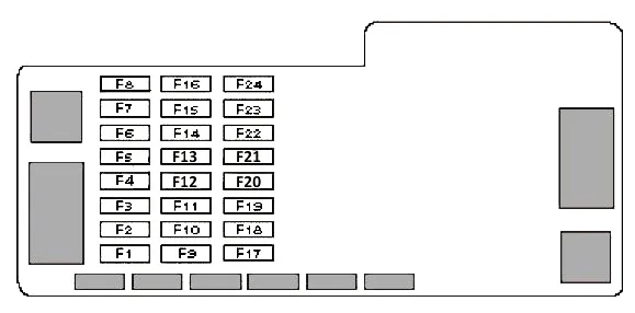
At the left end of the instrument panel, behind the protective cover, is the first block of fuses.
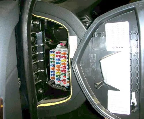
Check the purpose of the elements with your diagrams on the block cover.
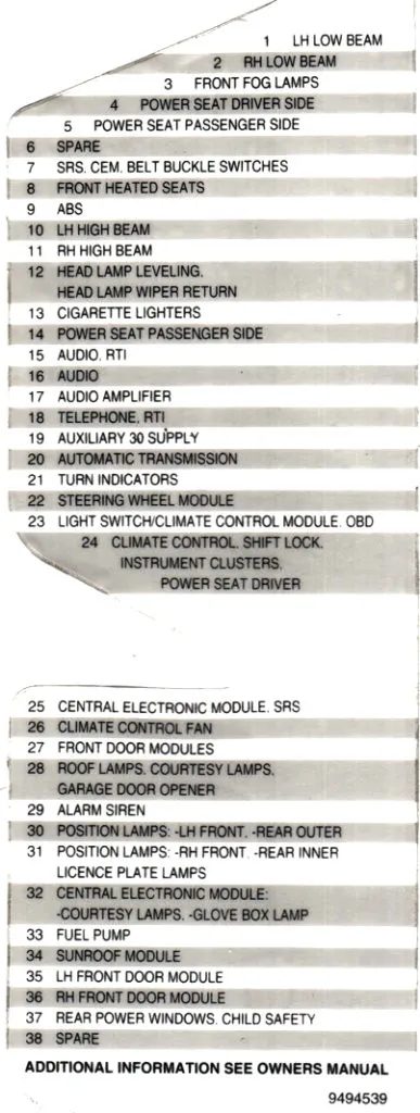
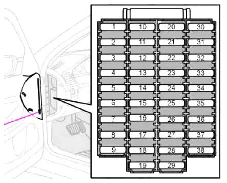
| F1 | (10A) Left headlight – low beam |
| F2 | (10A) Right headlight – low beam |
| F3 | (15A) Low Beam Headlight Relay / Fog Lights |
| F4 | (20A) High Beam Relay / (30A) Power Seat – Driver Side |
| F5 | (30A) Power Seat – Driver Side / Power Passenger Seat |
| F6 | (30A) Passenger seat electric drive |
| F7 | (15A) Front Seat Heater – Left (5A) Ignition Auxiliary Circuit Relay 1, Multifunction Control Module 1, SRS System, Seat Belt Warning System (^01/99) |
| F8 | (15A) Front seat heater – right (25A) Front seat heater |
| F9 | (5A) ABS system, steering wheel position control system unit |
| F10 | (15A) Left headlight – high beam |
| F11 | (15A) Right headlight – high beam |
| F12 | (15A) Headlight washer/wiper system, headlight range control |
| F13 | (20A) Cigarette Lighter/Charging Socket |
| F14 | (5A) Power Seat – Passenger Side, SRS, Seat Belt Warning |
| F15 | (5A) Audio system, navigation system |
| F16 | (20A) Audio system |
| F17 | (30A) Audio Output Amplifier |
| F18 | (15A) Fog lights (10A) Telephone, navigation system |
| F19 | (10A) Navigation system |
| F20 | (5A/15A) Additional equipment |
| F21 | (10A) Automatic transmission |
| F22 | (20A) Direction indicators/hazard warning lights (5A) Steering wheel switches – telephone/cruise control |
| F23 | (5A) Air conditioning control unit/heater control unit, combination switch-lighting, diagnostic socket, steering wheel switches |
| F24 | (10A) Electronic control unit for air conditioning/heating, additional heater, electric seat – driver’s side, instrument cluster |
| F25 | (10A) Ignition switch, multi-function control unit 1 |
| F26 | (30A) Air Conditioner/Heater Fan Motor Control Unit |
| F27 | (15A) Central locking, door open/door ajar indicators, electric/heated door mirrors, electric windows, door mirror lights |
| F28 | (10A) Multifunctional control unit 3, interior lights, vanity mirror |
| F29 | (10A) Telephone (5A) Anti-theft alarm sound |
| F30 | (10A) Front left side light, rear left side light, left side light |
| F31 | (10A) Front/rear side lights (right), right side light, number plate light |
| F32 | (10A) Multifunctional control unit 1, interior lights, vanity mirror |
| F33 | (15A) Fuel pump |
| F34 | (15A) Hatch |
| F35 | (25A) Front left side – central locking, electric window, electric door mirrors, open/door ajar indicators |
| F36 | (25A) Front right side – central locking, electric window, electric door mirror, open/door ajar indicators |
| F37 | (30A) Rear window lift motors, door locks against accidental opening – rear door |
| F38 | (5A) Anti-theft alarm sound |
Fuse number 13 is responsible for the operation of the cigarette lighter.
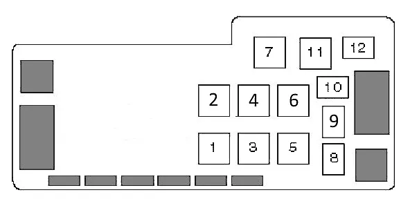
Relay block
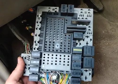
This unit is installed under the dashboard in early Volvo s80 models. Also known as the central electronic module CEM. It looks something like this:
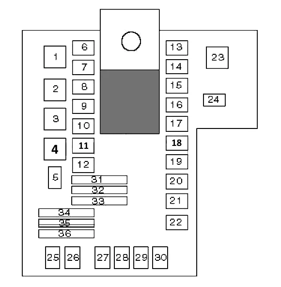
| 1 | — |
| 2 | Auxiliary ignition circuits |
| 3 | Main ignition circuits |
| 4 | — |
| 5 | — |
| 6 | Electric window lifter – closing, left rear door |
| 7 | Electric window lift – opening, left rear door |
| 8 | Disabling rear window lift motors, locking doors from accidental opening – rear doors |
| 9 | High beam headlights |
| 10 | Clearance lamps |
| 11 | Daytime lighting system |
| 12 | low beam headlights |
| 13 | Electric window relay – close, right rear door |
| 14 | Electric window relay – open, right rear door |
| 15 | Relay 2 auxiliary ignition circuits |
| 16 | Transmission control system |
| 17 | — |
| 18 | — |
| 19 | — |
| 20 | — |
| 21 | Telematics |
| 22 | — |
| 23 | — |
| 24 | — |
| 25 | — |
| 26 | — |
| 27 | Fog lights |
| 28 | Fuel pump relay |
| 29 | — |
| 30 | Fuel leakage control system relay |
| 31 | Jumper – left turn signals |
| 32 | Jumper – Right direction indicators |
| 33 | — |
| 34 | Jumper – low beam headlights |
| 35 | — |
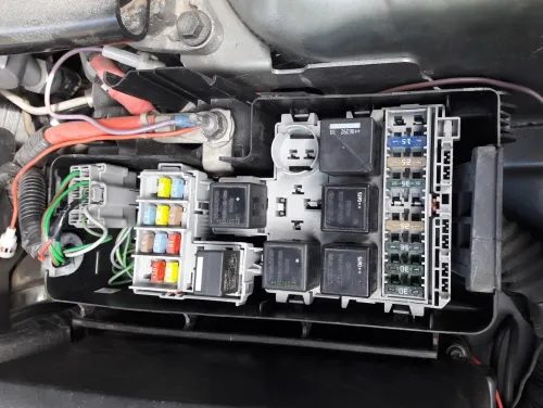
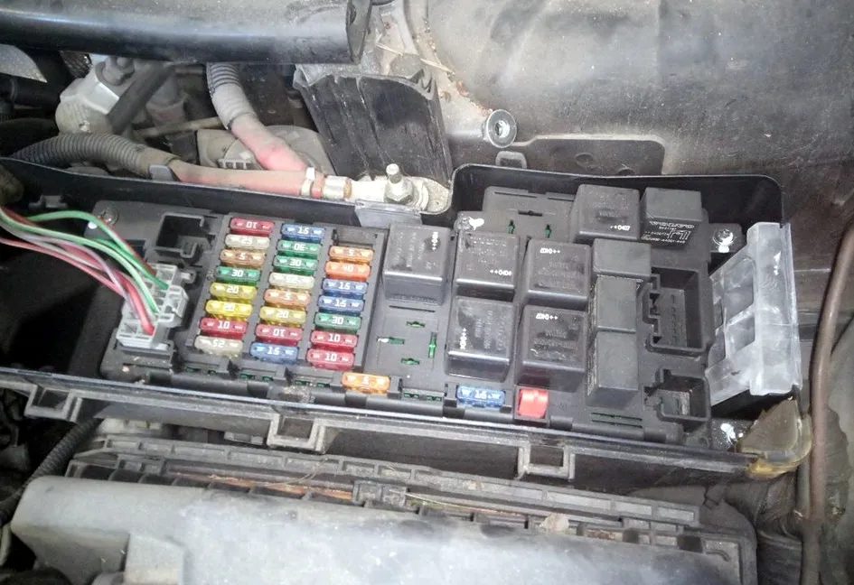
Block under the hood
On the left side of the engine compartment, next to the pillar, there is a block with fuses and relays. There are several possible versions of this block.
Option 1
| 1 | Air conditioning compressor electromagnetic clutch relay |
| 2 | — |
| 3 | — |
| 4 | Horn relay |
| 5 | Windshield wiper motor relay |
| 6 | — |
| 7 | — |
| 8 | Windshield wiper intermittent relay |
| 9 | Coolant Heater Relay 1 (Diesel) |
| 10 | Coolant Heater Relay 2 (Diesel) |
| 11 | Windshield Washer Pump Relay |
| 12 | — |
| 13 | — |
| 14 | — |
| 15 | — |
| 16 | Glow Plug Relay |
| 17 | — |
| 18 | — |
| 19 | Engine Management System Relay |
| 20 | — |
| 21 | — |
| 22 | — |
| 23 | Starter relay |
| F1 | (60A) Glow Plugs |
| F2 | (60A) F16(1998), Fuse/Relay Box-Instrument Panel 1 (F32-38), Front/Rear Side Lamp Relay |
| F3 | (60A) F9-10, Fuse/Relay Box-Instrument Panel 1(F3-6 and F16-19), Main Ignition Relay, Auxiliary Ignition Relay 2 |
| F4 | (60A) F11-13, Fuse/Relay Box-Instrument Panel 1 (F20-28) |
| F5 | — |
| F6 | — |
| F7 | (60A) F17-18, control unit for the electric motor of the cooling system fan |
| F8 | Not used (1998) |
| F9 | (20A) Headlight High Beam Relay |
| F10 | (15A) Headlight low beam relay |
| F11 | (5A) Brake lights |
| F12 | (25A) Windshield wiper |
| F13 | (15A) Headlamp Washer/Wiper System, Windscreen Washer Pump Relay |
| F14 | — |
| F15 | Not used (1998) |
| F16 | (15A) Horn (1998) |
| F17 | (25A) Additional heater |
| F18 | (25A) Additional equipment |
| F19 | (30A) Anti-lock brake system (ABS) |
| F20 | (30A) Anti-lock brake system (ABS) |
| F21 | (25A) Starter |
| F22 | (5A) Engine Control Module (ECM), Engine Management System Relay |
| F23 | Not used (1998) |
| F24 | (20A) Accelerator Pedal Position Sensor, Transmission Control Module (1998), Air Conditioning |
| F25 | (20A) Engine Management, Glow Plugs, Air Conditioning, Coolant Heater (Diesel), PCV Heater (Diesel) |
| F26 | (15A) Engine control |
| F27 | (20A) Heated Oxygen Sensors |
| F28 | (15A) Engine Management System, Crankcase Ventilation System Heater (Diesel) |
| F29 | (10A) Throttle Control Unit |
Option 2
Photo – example
| F1 | (25A) Additional heater |
| F2 | (15A) Additional equipment |
| F3 | — |
| F4 | (20A) Heated Oxygen Sensors |
| F5 | (15A) Engine Management System (Petrol) |
| F6 | (15A) Engine control |
| F7 | (10A) Throttle Control Unit |
| F8 | (10A) Accelerator pedal position sensor, air conditioning system |
| F9 | (15A) Sound signal |
| F10 | (10A) Rear Window Washer Pump Motor Relay |
| F11 | (20A) Engine management, glow plugs, air conditioning system, coolant heater (Diesel), crankcase ventilation heater |
| F12 | (5A) Brake lights |
| F13 | (25A) Windshield wiper |
| F14 | (30A) Anti-lock braking system/dynamic stability control and traction control |
| F15 | — |
| F16 | (15A) Headlamp Washer/Wiper System, Windscreen Washer Pump Relay |
| F17 | (15A) Headlights – low beam (S80 ^04/00) |
| F18 | (20A) Headlights – High Beam (S80^04/00) |
| F19 | (30A) Anti-lock braking system/dynamic stability control and traction control |
| F20 | (30A) Coolant Heater Relay 2 – Diesel |
| F21 | (30A) Coolant Heater Relay 1 – Diesel |
| F22 | (25A) Starter relay |
| F23 | (5A) Engine Management System Relay, Engine Control Module (ECM) |
| F24 | — |
Relay diagram
- Coolant Heater Relay 1 (Diesel)
- Engine Management System Relay
- Glow Plug Relay
- Starter relay
- Windshield wiper intermittent relay
- Relay of two-component fuel supply system Bi-fuel
- Coolant Heater Relay 2 (Diesel)
- Air conditioning compressor electromagnetic clutch relay
- Horn relay
- Windshield Washer Pump Relay
- Windshield wiper motor relay
- Rear Window Washer Pump Motor Relay
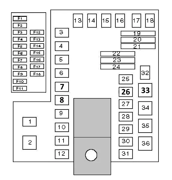
Block in the trunk
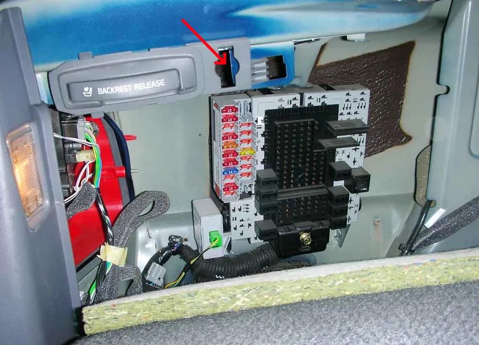
In the luggage compartment, on the left behind the passenger compartment protection, another block with fuses and relays is installed. To access it, you need to turn the holder.
The block itself will look something like this.
| 1 | — |
| 2 | — |
| 3 | — |
| 4 | Rear window wiper motor |
| 5 | — |
| 6 | — |
| 7 | Trunk lid/rear door opening drive relay) |
| 8 | Trunk lid/rear door opening drive relay^80), trunk lid/rear door lock drive relay (V70) |
| 9 | Fuel filler door lock actuator relay – opening |
| 10 | Fuel filler flap/lid actuator relay – closing |
| 11 | Right rear door central locking relay – unlocking |
| 12 | Central lock relay right rear door – blocking |
| 13 | Headrest Drive Relay – Rear |
| 14 | Rear Window Wiper Motor Relay |
| 15 | — |
| 16 | — |
| 17 | — |
| 18 | — |
| 19 | Jumper – brake lights |
| 20 | Jumper – rear dimensions |
| 21 | Jumper – rear dimensions |
| 22 | Jumper – power connector for additional equipment in the luggage compartment^0) |
| 23 | Jumper – fog lights |
| 24 | — |
| 25 | Rear Fog Light Relay – Trailer |
| 26 | Rear Fog Light Relay |
| 27 | Brake light relay |
| 28 | Reverse Light Relay |
| 29 | Central lock relay, rear – double locking |
| 30 | Left Rear Door Central Locking Relay – Unlocking |
| 31 | Left rear door central lock relay – blocking |
| 32 | — |
| 33 | — |
| 34 | Rear Window Defogger Relay |
| 35 | — |
| 36 | Trailer Electrical Equipment Socket Power Relay |
| F1 | (10A) Multi-function control unit 2, interior lighting-luggage compartment lighting^80) |
| F2 | (10A) Rear fog lights |
| F3 | (15A) Brake lights |
| F4 | (10A) Reversing lights |
| F5 | Not used (^01/99) |
| F6 | (10A) Trunk/Tailgate Lock |
| F7 | (10A/15A) Rear seat head restraints^80), auxiliary power socket in luggage compartment |
| F8 | (15A) Central locking – rear doors, fuel filler flap/cap |
| F9 | (20A) Trailer electrical equipment socket |
| F10 | (10A) Audio system, navigation system |
| F11 | (15A) Additional equipment |
| F12 | not used (S80) |
| F13 | not used (S80) |
| F14 | — |
| F15 | Not used (^01/99) |
| F16 | Not used (^01/99) |
| F17 | — |
| F18 | — |
Another block with high-power fuses may be installed next to the battery.