The 9th generation Mitsubishi Galant was produced in 2004, 2005, 2006, 2007, 2008, 2009, 2010, 2011 and 2012. In our material, we will show a description of the fuses and relays of the 9th generation Mitsubishi Galant with block diagrams and their locations. We will highlight the cigarette lighter fuse.
There may be differences between the material presented and your implementation. Please check the designations with your diagrams or other technical documentation.
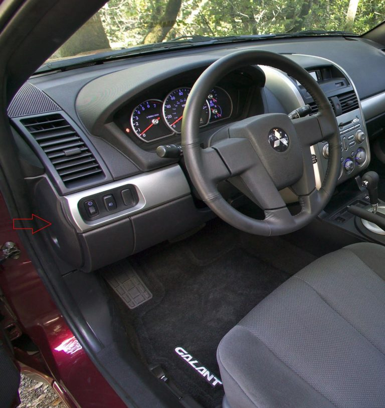
Cabin block
Located at the end of the instrument panel behind a protective cover.
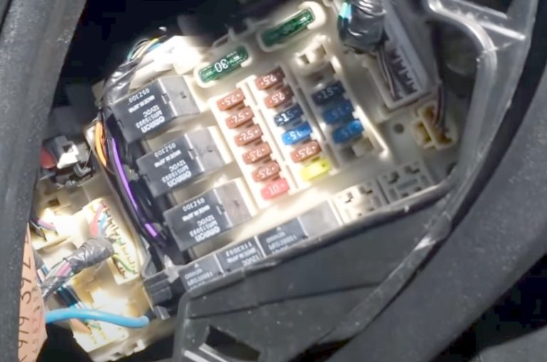
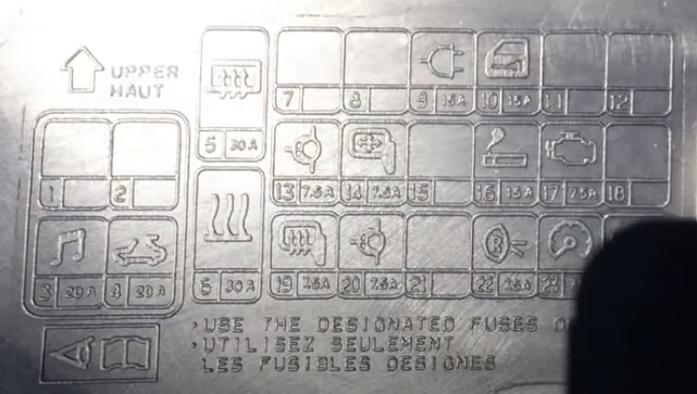
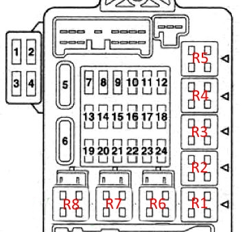
Fuse description
| 1 | Reserve |
| 2 | Reserve |
| 3 | 30A Audio system amplifier |
| 4 | 20A Sunroof assembly |
| 5 | 30A Rear window heater, Overcurrent condenser interference. |
| 6 | 30A Heater fan motor |
| 7 | Reserve |
| 8 | Reserve |
| 9 | 15A Connector for connecting additional electrical equipment |
| 10 | 15A Diagnostic connector, Central locking, ETACS control unit |
| 11 | ETACS control unit |
| 12 | Reserve |
| 13 | 7.5A Electrochromic rear-view mirror; |
| 14 | 7.5A Electric side mirror drives |
| 15 | Reserve |
| 16 | 15A Cigarette lighter |
| 17 | 7.5A Fuel pump relay; engine control unit and automatic transmission |
| 18 | Reserve |
| 19 | 7.5A Rear view mirror heaters |
| 20 | 7.5A Relay |
| 21 | Reserve |
| 22 | 7.5A Rear combination lights, Automatic transmission control |
| 23 | 7.5A Multifunction display, Steering column switch, Control units (ABS, ETACS, SRS) |
| 24 | 10A Ignition coil |
Fuse number 9 at 15A is responsible for the cigarette lighter.
Relay decoding
- Fuel pump relay (1)
- Relay socket for connecting additional equipment
- Fuel pump relay (2)
- Front seat heating relay
- Rear fog light relay
- Electric window lift relay
- Heater fan motor relay
- Rear window heater relay
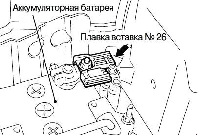
Blocks under the hood
Located on the left side of the engine compartment next to the battery.
Photo example
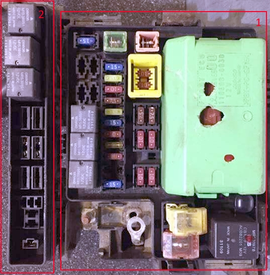
The green section is the electronic lighting control unit.
Main unit
Scheme
Purpose of fuses
| 1 | 80A Battery |
| 2 | 30/50A Cooling system fan motor |
| 3 | 60A ABS system |
| 4 | 40A Ignition switch circuits |
| 5 | 30A Electric window regulator |
| 6 | 15A Fog lights |
| 7 | 15A/20A Seat heater |
| 8 | 20A Audible signal |
| 9 | 20A Engine management system |
| 10 | 10A Air Conditioner Compressor Electromagnetic Clutch |
| 11 | 15A Stop signals |
| 12 | 10A Rear fog lights |
| 13 | 7.5A Generator |
| 14 | 10A Emergency alarm |
| 15 | 20A Electronic gearbox control unit |
| 16 | 10A Right headlight high beam |
| 17 | 10A Left headlight high beam |
| 18 | 10A Right headlight low beam |
| 19 | 10A Left headlight low beam |
| 20 | 7.5A Dimensions right |
| 21 | 7.5A Dimensions left |
| 22 | 10A Interior lights |
| 23 | 10A Audio system |
| 24 | 15A Fuel pump |
| 25 | 30A Glass cleaner |
Relay designation
- Fog light relay
- Windshield heater relay
- Accessory power connector relay
- Horn relay
- Fog light relay
- Cooling system fan motor relay
Relay block
Scheme
Description
- Air conditioner compressor electromagnetic clutch relay
- Engine control system relay
- Electronic gearbox control unit relay
- Ignition relay
- Throttle control unit relay
- Reserve
- Reserve
Main fuse
The main fuse is a high-power fuse located on the positive terminal of the battery.
Separately, outside the presented blocks, additional relays can be attached, for example: a relay for the condenser fan motor and the air conditioner fan and an audio system fuse.