The Mitsubishi Outlander 1st generation crossover was produced in 2001, 2002, 2003, 2004, 2005, 2006, 2007 and 2008 and was delivered worldwide. Also known as the Mitsubishi Airtrek and Montero Outlander. In this material we will show a description of the fuses and relays of the Mitsubishi Outlander 1 (Airtrek) with block diagrams and their locations. We will highlight the cigarette lighter fuse.
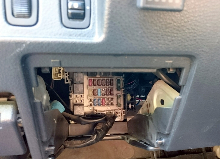
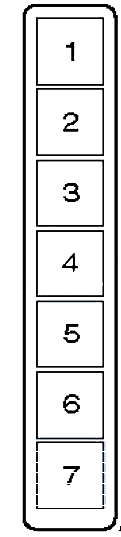
Cabin block
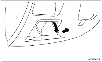
It is located behind the glove box at the bottom of the instrument panel.
Check the assignment with your diagrams.
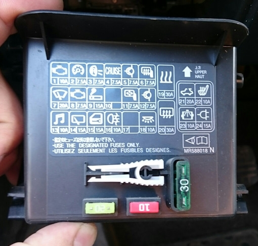
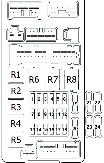
Fuse description
| 1 | 10A Ignition system |
| 2 | 7.5A Instrument cluster (panel) |
| 3 | 7.5A Reversing lights, Automatic transmission control relay |
| 4 | 7.5A Cruise control |
| 5 | 7.5A Air conditioning system |
| 6 | 7.5A Exterior mirror control |
| 7 | 20A Wipers and washers, Electronic lighting control unit |
| 8 | 7.5A Electronic engine and automatic transmission control unit (for vehicles with automatic transmission), electronic engine management system unit, fuel pump relay |
| 9 | 15A Cigarette lighter |
| 10 | Reserve |
| 11 | 7.5A Electric mirror drive |
| 12 | 7.5A ABS |
| 13 | 10A Audio system, Radio |
| 14 | 15A Rear window wiper/washer |
| 15 | 15A Diagnostic connector |
| 16 | 10A Rear fog light |
| 17 | Reserve |
| 18 | 10A Interior lights |
| 19 | 30A Heater fan motor |
| 20 | 30A Rear window heater |
| 21 | 20A Sunroof drive motor |
| 22 | 10A Seat heater |
| 23 | 10A Turbocharger intercooler cooling pump |
| 24 | Reserve |
Fuse number 9 at 15A is responsible for the cigarette lighter.
Relay decoding
- Fuel pump relay (1)
- Front seat heating relay
- Fuel pump relay (2)
- Relay socket for connecting additional equipment
- Rear fog light relay
- Electric window lift relay
- Heater fan motor relay
- Rear window heater relay
Blocks under the hood
Installed in the left side of the engine compartment. Consists of a main fuse and relay block and a relay block

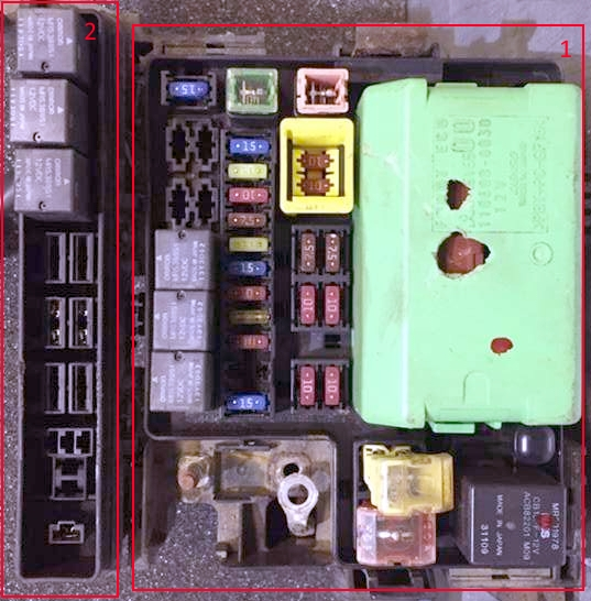
Main unit
Scheme
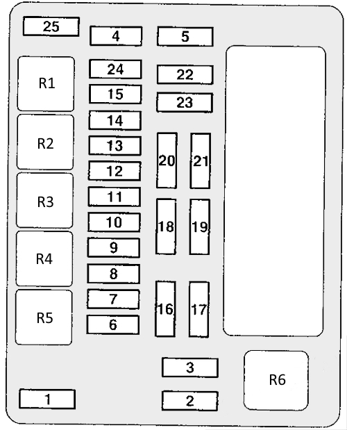
Purpose of fuses
| 1 | 60A Fuse/Relay Box in the Instrument Panel |
| 2 | 50A Cooling system fan motor |
| 3 | 60A ABS system |
| 4 | 40A Ignition switch circuits |
| 5 | 30A Electric window regulator |
| 6 | 15A Fog lights |
| 7 | 15A/20A Seat heater |
| 8 | 10A Audible signal |
| 9 | 20A Engine management system |
| 10 | 10A Air Conditioner Compressor Electromagnetic Clutch |
| 11 | 15A Stop signals |
| 12 | 15A Windshield heater |
| 13 | 7.5A Generator |
| 14 | 10A Emergency alarm |
| 15 | 20A Electronic gearbox control unit |
| 16 | 10A Right headlight high beam |
| 17 | 10A Left headlight high beam |
| 18 | 10A Right headlight low beam |
| 19 | 10A Left headlight low beam |
| 20 | 7.5A Tail light (right) |
| 21 | 7.5A Tail light (left) |
| 22 | 10A Interior lights |
| 23 | 10A Audio system |
| 24 | 15A Fuel pump |
| 25 | 15A Accessory power connector |
Relay designation
- Reserve
- Windshield heater relay
- Accessory power connector relay
- Horn relay
- Fog light relay
- Cooling system fan motor relay
Relay block
Scheme
Description
- Air conditioner compressor electromagnetic clutch relay
- Engine control system relay
- Electronic gearbox control unit relay
- Ignition relay
- Throttle control unit relay
- Reserve
- Reserve
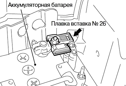
Main fuse
The main fuse is a high-power fuse located on the positive terminal of the battery.