Mitsubishi Lancer 10th generation was produced in 2007, 2008, 2009, 2010, 2011, 2012, 2013, 2014, 2015, 2016, 2017 with engines of 1.5 1.6 1.6. During this time, the model has undergone restyling. Mitsubishi Lancer Evolution or Mitsubishi Lancer Evo is a sports version of the Lancer model range. In this article we will show a description of the fuses and relays of the Mitsubishi Lancer 10 with block diagrams, photos – examples of execution and their locations. We will note the fuse responsible for the cigarette lighter.
Cabin block
Located under the driver’s dashboard behind a protective cover.
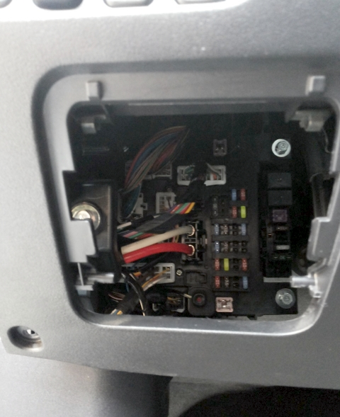
Check the assignment with your diagrams on the back of the protective cover.
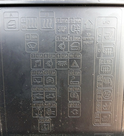
Photo – an example of a circuit from the block cover
Fuse description
| 1 | 30A Heater/heater |
| 2 | 15A Stop signals |
| 3 | 10A Rear fog light |
| 4 | 30A Windshield wiper glass |
| 5 | Reserve |
| 6 | 10A Accessory circuit |
| 7 | 20A Door locks |
| 8 | 15A Audio system |
| 9 | 7.5A Accessory circuit |
| 10 | 15A Interior lights |
| 11 | 15A Emergency light alarm |
| 12 | 15A Glass window cleaner tailgate |
| 13 | 7.5A Control and measuring instruments |
| 14 | Reserve |
| 15 | 15A Cigarette lighter (front power outlet) |
| 16 | 10A Ignition switch |
| 17 | 20A Electric sunroof drive |
| 18 | Reserve |
| 19 | 10A Exterior rear-view mirrors |
| 20 | 10A All-wheel drive system |
| 21 | 7.5A Reversing lights |
| 22 | Reserve |
| 23 | 15A Additional power outlet |
| 24 | 30A Power windows |
| 25 | 30A Heated tailgate glass |
| 26 | 7.5A Exterior rear view mirror heaters |
| 27 | 15A Power supply |
| 28 | 20/25A Electric seats |
| 29 | 30A Seat heating |
Fuse number 15 is responsible for the cigarette lighter, and fuse number 23 at 15A is responsible for the socket.
Relay purpose
- Door lock relay
- Heater relay
- Seat heating relay
- Glass heating relay
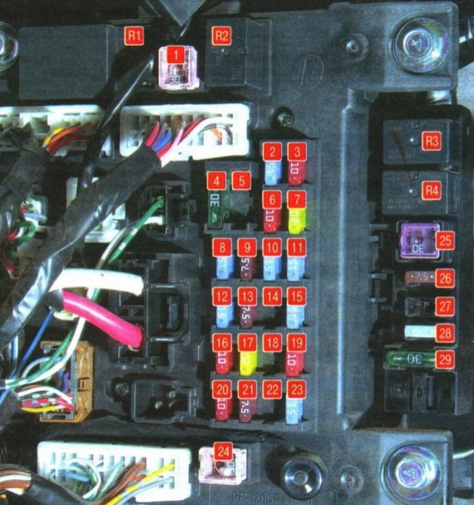
Blocks under the hood
Main unit
It is installed in the left part of the engine compartment.
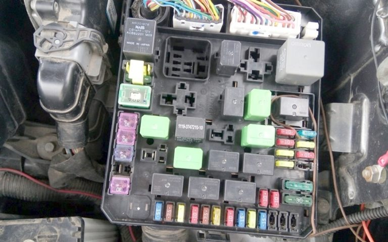
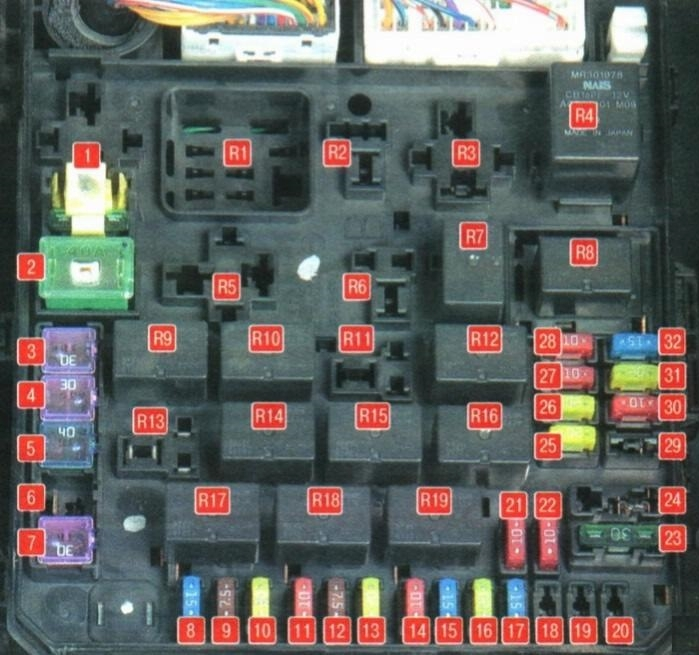
Fuse designations
| 1 | 30A Input/Output Device |
| 2 | 40A Cooling system fan motor |
| 3 | 30A Condenser fan motor |
| 4 | 30A ABS |
| 5 | 40A ABS |
| 6 | Reserve |
| 7 | 30A Starter |
| 8 | 15A Front fog lights |
| 9 | 7.5 Engine control |
| 10 | 20A AKP |
| 11 | 10A Audible signal |
| 12 | 7.5A Generator |
| 13 | 20A Headlight washer |
| 14 | 10A Air conditioner |
| 15 | 15A Throttle |
| 16 | 20A Anti-theft alarm sound |
| 17 | 15A Wiper blade heater |
| 18 | Reserve |
| 19 | 30A Electric tailgate |
| 20 | 10A Daytime exterior lighting system |
| 21 | 10A High beam headlight (left) |
| 22 | 10A High beam headlight (right) |
| 23 | 30A Audio system amplifier |
| 24 | 30A Diesel engine electrical equipment |
| 25 | 20A Left dipped beam headlight (with gas discharge lamps) |
| 26 | 20A Right dipped beam headlight (with gas discharge lamps) |
| 27 | 10A Left dipped beam headlight (with halogen bulbs) |
| 28 | 10A Right dipped beam headlight (with halogen bulbs) |
| 29 | 10A Engine electrical equipment power supply circuit |
| 30 | 10A Ignition coil |
| 31 | 20A Engine electrical equipment power supply circuit |
| 32 | 15A Fuel pump |
Relay decoding
| R1 | Glow plug relay (for diesel engines) |
| R2 | Radiator fan relay |
| R3 | Heater relay |
| R4 | Engine control system relay |
| R5 | Stability control relay |
| R6 | Air conditioner radiator fan relay |
| R7 | Engine control system relay |
| R8 | Headlight low beam relay |
| R9 | Engine control system relay |
| R10 | Wiper blade heater relay |
| R11 | Daytime exterior lighting system relay |
| R12 | Engine control system relay |
| R13 | Anti-theft alarm relay |
| R14 | Automatic transmission relay |
| R15 | Headlight Washer Relay |
| R16 | Headlight high beam relay |
| R17 | Front fog light relay |
| R18 | Horn relay |
| R19 | Air conditioner relay |
Relay block
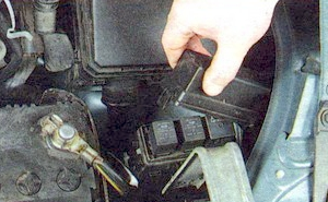
Located next to the main one.
Scheme
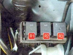
- R1 Engine cooling fan low speed relay
- R2 Air conditioner fan relay
- R3 Engine cooling fan high speed relay
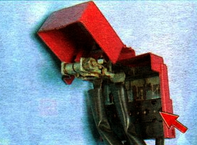
Battery pack
On the positive terminal of the battery there is a high-power fuse block in the form of fuse links.
Scheme
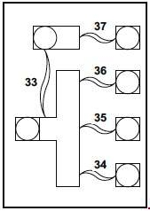
Appointment
- 33 – 120A Fuse link No. 37/ Fuse links No. 34-36
- 34 – 80A Fuses No. 2, 4, 5, 10, 11, 12, 14, 15, 17, 18, 23, 24, 25 and fuse jumper No. 20 in the passenger compartment, and ETACS-ECU
- 35 – 80A Reserve
- 36 – 120A Fuses No. 1-23, 30-32 and fuses No. 24-29 in the engine compartment, engine control relay, headlight relay (high beam) and headlight relay (low beam)
- 37 – 80A Fuses No. 1 and 21, fuses No. 3, 6, 13, 16, 19, 22 in the passenger compartment, fan relay and ETACS-ECU