Kia Cerato 2nd generation was produced in 2008, 2009, 2010, 2011, 2012 and 2013. In Europe and the USA it is known as Kia Forte . In this article you will find a description of fuses and relays of Kia Cerato 2nd generation with block diagrams, their locations and photos – examples of execution. We note the fuse responsible for the cigarette lighter.

The purpose of the elements in the blocks may differ from the one presented and depends on the year of manufacture, equipment level and country of delivery. Compare the description with your diagram on the back of the protective cover.
Blocks in the cabin
Fuse block
It is located on the left end of the instrument panel, on the driver’s side, behind a protective cover.
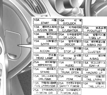
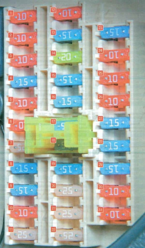
Description
| 1 | 10A Starter relay, anti-theft alarm – START |
| 2 | 10A Air conditioning control unit – A/CON SW |
| 3 | 10A Heated exterior rear-view mirror system – HTD MIRR |
| 4 | 15A Seat heating – SEAT HTR |
| 5 | 10A Air conditioner – A/CON |
| 6 | 10A High beam lamps – HEAD LAMP |
| 7 | 25A Windshield wiper – FR WIPER |
| 8 | 10/15A Rear wiper or reserve |
| 9 | 15A Door lock and ignition control unit – DRl/SMK |
| 10 | 10A Rear fog lights – RR FOG |
| 11 | 25A Power window control unit – P/WDW DR |
| 12 | 10A Clock – D CLOCK |
| 13 | 15A Cigarette lighter – C/LIGHTER |
| 14 | 20A Sunroof, ignition control unit relay – DR LOCK |
| 15 | 15A Windshield Defroster Relay – DEICER |
| 16 | 15A Stop – signals – STOP LP |
| 17 | 15A Interior lighting ROOM LP |
| 18 | 15A Audio system, trip computer – AUDIO |
| 19 | 15A Trunk opening drive relay – TRUNK OPEN |
| 20 | 25A Passenger Door Electronics Control Module – PDM |
| 21 | 25A Power window lock – SAFETY P/WDW |
| 22 | 25A Power windows – P/WDW ASS |
| 23 | 15A Power Outlet – P/OUTLET |
| 24 | 10A Switch Block – T/SIG LP |
| 25 | 10A Airbag warning light – A/BAG IND |
| 26 | 10A Instrument panel – CLUSTER |
| 27 | 15A Airbag – A/BAG |
| 28 | 15A Door lock and ignition control unit – IGN1-A |
| 29 | 15A Hazard alarm relay – HAZARD LP |
| 30 | 10A Right rear position light bulb – TAIL LP (RH) |
| 31 | 10A Left rear position light bulb – TAIL LP (LH) |
Fuse number 13 at 15A is responsible for the cigarette lighter.
Relay block
Located under the panel in a single junction box of a modular integrated circuit.
There may be the following relays:
- launch keys
- illumination (illuminations)
- glass cleaner
- glass heater
- without key access
- electric window lifts
- etc.
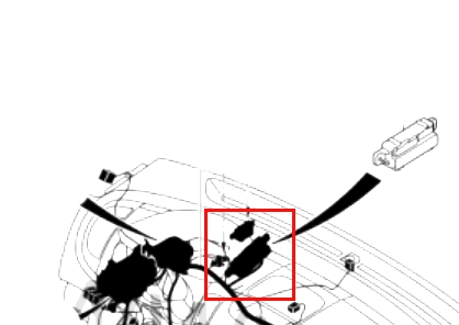
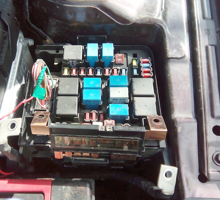
Block under the hood
Located in the left part of the engine compartment, next to the battery, under a protective cover.
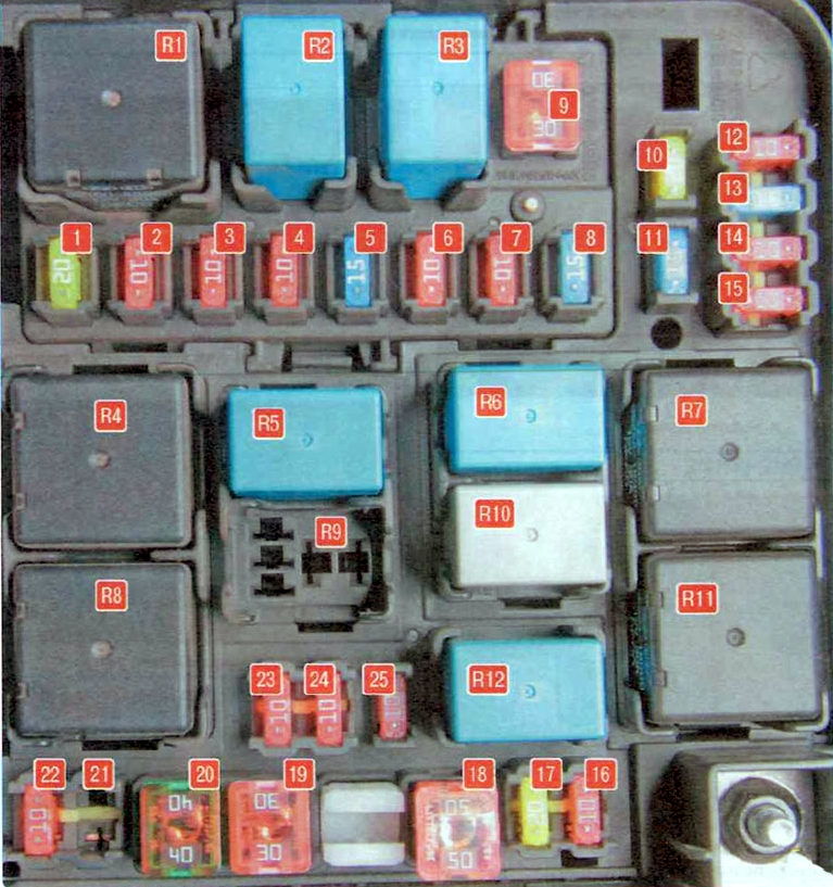
Fuse designations
| 1 | 20A Ignition coils, capacitor – IGN COIL |
| 2 | 10A Engine Management System Sensors – SNSR2 |
| 3 | 10A Ignition system – ECU2 |
| 4 | 10A Air conditioning system, fuel injectors – INJECTOR |
| 5 | 15A Engine Management System Sensors – SNSR1 |
| 6 | 10A Main relay – ECU1 |
| 7 | 10A Air conditioner – A/CON |
| 8 | 15A Fuel Pump – F/PUMP |
| 9 | 30A Main relay – ECU |
| 10 | 20A Reserve – SPARE |
| 11 | 15A Reserve – SPARE |
| 12 | 10A Reverse light switch – B/UPLP |
| 13 | 15A Ignition coils, capacitor – ECU3 |
| 14 | 10A ESP stability control system, ABS anti-lock braking system, ABS stability control sensor |
| 15 | 10A Engine Management System Sensors – SNSR3 |
| 16 | 10A Sound signal – HORN |
| 17 | 20A High beam – H/LPHI |
| 18 | 50A Electronic control unit for interior electrical equipment – BATT2 |
| 19 | 30A Ignition switch – IGN 1 |
| 20 | 40A ESP stability control system, ABS anti-lock braking system, diagnostic connector – ABS1 |
| 21 | 20A Reserve – SPARE |
| 22 | 10A Fog lights, diagnostic connector – FOG LP (FR) |
| 23 | 10A Left headlight low beam bulb – H/LP LO LH |
| 24 | 10A Right headlight low beam bulb – H/LP LO RH |
| 25 | 10A Reserve – SPARE |
Relay purpose
- MAIN – Main relay
- F/PUMP – Fuel Pump Relay
- A/C0N – Air conditioning relay
- BLOWER – Cooling system radiator electric fan relay
- H/LPHI – Headlight high beam relay
- HORN – Horn relay
- C/FAN HI – Air conditioning electric fan relay (high speed)
- START – Starter relay
- FOG LP – Rear fog lamp relay
- WIPER — Wiper Relay
- C/FAN LO – Air conditioning electric fan relay (low speed)
- H/LPLO – Headlight low beam relay
Main unit
On the side, on the front wall, there is the main fuse block, made in the form of high-power fuse links.
Scheme
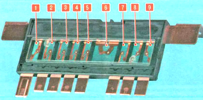
Transcript
- 80A MDPS – EPS Control Unit
- 40A ABS2 – ABS control unit, ESP control unit
- 40A C/FAN – Air conditioning system electric fan
- 40A BLOWER – Electric cooling system radiator fan
- 40A HTD GLASS – Heated rear-view mirrors
- 125A ALT – Generator
- 30A IGN2 – Ignition switch (lock)
- 50A VAT 1 – Electronic control unit for interior electrical equipment
- 50A SPARE – Reserve