Spark is a small-capacity city car of class A. The model was developed by the South Korean division of General Motors (Daewoo) and presented in 2005. This is the smallest car among the manufacturer’s models. In this material, we will consider in detail the fuse diagrams of the Chevrolet Spark 2nd generation ( M200 ) 2005, 2006 release.
The information on the diagrams is relevant for the Chevrolet Spark 2nd generation (M200) models produced in 2005 and 2006.
In the salon
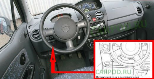
Located on the driver’s side, at the bottom of the dashboard.
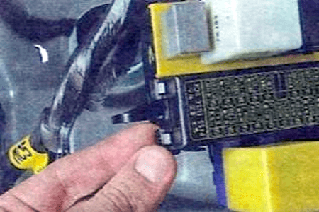
To access it, you need to squeeze the latches and remove the cover.
| Cabin block diagram |
|---|
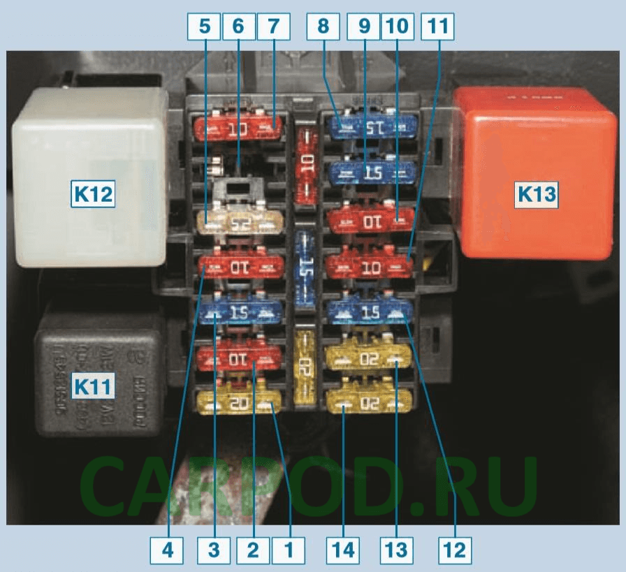
| No. | Description | Current, A |
| 7 | Instrument cluster instruments and control lamps, clock, immobilizer, security alarm | 10 |
| 6 | Airbag (optional) | 10 |
| 5 | Electric windows | 25 |
| 4 | Direction indicator lamps and direction indicator lamps | 10 |
| 3 | Brake light bulbs | 15 |
| 2 | Audio system | 10 |
| 1 | Spark cigarette lighter fuse | 20 |
| 8 | Windscreen cleaner | 15 |
| 9 | Tailgate glass wiper, windshield and tailgate glass washers, reversing light | 15 |
| 10 | Electric drive of the outside rearview mirror | 10 |
| 11 | Audio system, interior and luggage compartment lights, open door indicator light in instrument cluster, immobilizer | 10 |
| 12 | Continuous power supply for the hazard warning lights when the ignition is off, hours | 15 |
| 13 | Electric door lock drives (central lock) | 20 |
| 14 | Starter solenoid relay | 20 |
| Purpose of relay modules | ||
| K11 | Direction indicator and hazard warning relay | |
| K12 | Windshield wiper relay | |
| K13 | Fog light relay in rear light | |
In the engine compartment
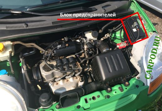
Located on the left side of the engine compartment.
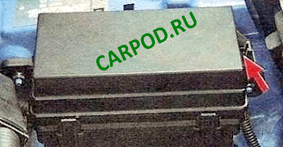
To access the fuses, you need to press the latch and remove the protective cover.
Spark engine block elements diagram
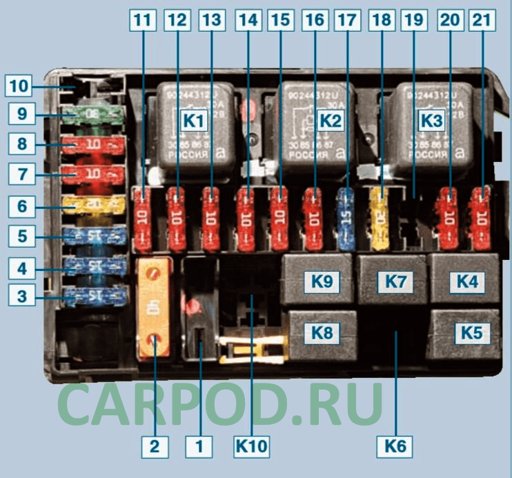
| No. | Transcript | Current, A |
| 1 | ABS brakes (optional) | 50 |
| 2 | All consumers are powered regardless of the position of the key in the ignition switch (constant power supply) | 40 |
| 21 | Gasoline pump | 10 |
| 20 | Power supply of the ECU from the ignition switch, fuel pump relay winding, ABS unit (optional), generator pre-excitation (at start-up), terminal “B” of the ignition coil unit, speed sensor | 10 |
| 19 | Spare | 10 |
| 18 | Electric heater fan | 20 |
| 17 | Rear door glass heating element | 15 |
| 16 | Right headlight high beam | 10 |
| 15 | Left headlight high beam | 10 |
| 14 | Right low beam headlight | 10 |
| 13 | Low beam left headlight | 10 |
| 12 | Side light of the right headlight and right rear light | 10 |
| 11 | Left headlight, left rear light and number plate light | 10 |
| 10 | Air conditioning compressor clutch (optional) | 10 |
| 9 | Electric fan of the cooling system | 30 |
| 8 | Spare | 10 |
| 7 | Sound signal | 10 |
| 6 | Power supply for headlight relay, high beam switch | 20 |
| 5 | Constant power supply to the ECU, winding of the main relay, winding of the air conditioning compressor clutch relay, winding of the high-speed relay of the electric cooling fan, winding of the low-speed relay of the electric cooling fan, oxygen concentration and camshaft position sensors, fuel injectors, exhaust gas recirculation and canister purge valves, power supply to the fuel pump relay | 15 |
| 4 | Fog lights | 15 |
| 3 | Spare | 15 |
| Purpose of relay modules | ||
| K1 | High Speed Cooling Fan Relay | |
| K2 | Main relay | |
| KZ | Heater Fan and Rear Door Glass Heating Relay | |
| K4 | Fog light relay | |
| K5 | Fuel pump relay | |
| K6 | Horn relay (optional) | |
| K7 | Low speed relay for radiator cooling fan | |
| K8 | Headlight relay | |
| K9 | Outdoor lighting relay | |
| K10 | Air Conditioning Compressor Relay | |